Cisco CRS-1 - Carrier Routing System Router, Hardware Installation Manual
Introducing the Cisco CRS-1 - a cutting-edge Carrier Routing System Router built to elevate your network performance. Seamlessly manage and customize your device with the comprehensive Configuration Manual, available for free download from manualshive.com. Enhance your user experience with this exceptional product, designed to empower your network capabilities.
Share
Download


Reviews:
No comments
Related manuals for CRS-1 - Carrier Routing System Router

CB4DRQ
Brand: Wuntronic Pages: 48

1261B
Brand: Racal Instruments Pages: 185

ION219 Series
Brand: Lantronix Pages: 36

7704
Brand: Chassisworks Pages: 106

R720LPB
Brand: Supermicro Pages: 66

SC113M Series
Brand: Supermicro Pages: 83

AFF A700
Brand: NetApp Pages: 1672

Modular Matrix 38250
Brand: Lindy Pages: 8
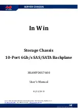
3RAMPD017600
Brand: In Win Pages: 9
IW-RF100
Brand: In Win Pages: 15
101 TUF GAMING
Brand: In Win Pages: 15
IW-RS316-02M
Brand: In Win Pages: 20

LB440GX
Brand: Intel Pages: 26

SC5275-E BRP
Brand: Intel Pages: 34

SC1400UP
Brand: Intel Pages: 82

C50277-001
Brand: Intel Pages: 73

Astor II
Brand: Intel Pages: 76

P4304XXMFEN2
Brand: Intel Pages: 108


