CIS VCC-FC60FR19CL, Operational Manual
Introducing the CIS VCC-FC60FR19CL - a cutting-edge device designed to revolutionize your user experience! Unlock the full potential of this remarkable product with our comprehensive Operational Manual. Available for free download at manualshive.com, this manual offers detailed instructions, ensuring hassle-free setup and optimum performance.
Share
Download


Reviews:
No comments
Related manuals for VCC-FC60FR19CL

E-1 - Digital Camera SLR
Brand: Olympus Pages: 2

LPC Series
Brand: Okina Pages: 3
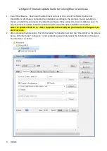
Z3
Brand: Z-EDGE Pages: 4

Lumix S-E2470
Brand: Panasonic Pages: 38

DCC-608DV
Brand: D-MAX Pages: 8

CAMCOLMBLAH2
Brand: Velleman Pages: 17

PAS X-plore
Brand: Dräger Pages: 2
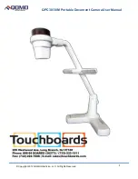
QPC 30M
Brand: Qomo Pages: 10

NVIP-1DN3000H/IR-1P-II
Brand: Novus Pages: 32

HN-DPF1001
Brand: Feelcare Pages: 11

Z3Cam-HD
Brand: Z3 Technology Pages: 6

CAMEDIA C-5060 Wide Zoom
Brand: Olympus Pages: 289

CC-4707WS-21
Brand: Crest Audio Pages: 2

FT-FAT200
Brand: FlashTiming Pages: 3

N3-506
Brand: Nextar Pages: 17

ZX-50
Brand: Pentax Pages: 104

TR-D2181IR3
Brand: TRASSIR Pages: 2
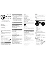
WV-CF112E
Brand: Panasonic Pages: 2


