Chauvet Slim Par Pro TRI, User Manual
The Chauvet Slim Par Pro TRI is a versatile lighting fixture that offers vibrant colors and a compact design. To make the most of its features, don't forget to download the comprehensive User Manual for free, available exclusively at manualshive.com. Discover the endless possibilities and unleash your creativity with this powerful lighting tool.
Share
Download


Reviews:
No comments
Related manuals for Slim Par Pro TRI
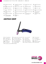
ABITIG GRIP 1502
Brand: Abicor Binzel Pages: 168

9 260 Series
Brand: Fein Pages: 150

Sync Core HL-NW100RC
Brand: Cateye Pages: 13

FXLD136RGB
Brand: Lightronics Pages: 6

MATRIX 100 W
Brand: Cameo Pages: 52

9430 RALS
Brand: Pelican Pages: 2

962437
Brand: BAREBO Pages: 8

linea m eco pure White
Brand: BION TECHNOLOGIES Pages: 24

ERLEDB
Brand: LIGHTSAFE Pages: 2

Metrex Egress METEC Series
Brand: kenall Pages: 3
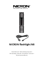
N8
Brand: Nicron Pages: 26

IW108-RGBW
Brand: Dialighting Pages: 6

WLED2030
Brand: Arlec Pages: 2

HL15
Brand: Arlec Pages: 2

Slim PAR TRI 12 IRC
Brand: Chauvet Pages: 18

Cut 61 PT100
Brand: Jasic Pages: 18

FUSION QXV
Brand: showtech Pages: 20

A7
Brand: Wowtac Pages: 2


