1
Service
Access
Door
4.5
4.5
5.88
8.88
Output
Shaft
ARTICULATED ARM
GATE OPERATORS
MODEL BG770
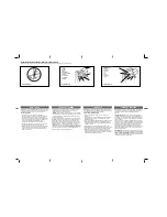
INSTALLATION
Drill 1/2" diameter hole 4-1/2" up from the center of the output
shaft and 4-1/2" back from the center of the output shaft
(Figure 1).
Attach gate arm (lower) to arm hub fl ange (Figure 2).
1
2
CARTON INVENTORY
PART #
ITEM
QTY
01-G0711
Installation Instructions
1
07-8043
1" O.D. x 1/2" I.D. x 1-1/2"L Spacer
1
10-8041
Hinge Plate
2
12-8041
3/4" O.D. x 3/8" I.D. x 7/8"L Spacer
2
12-8049
Female Rod End
2
82-HN38-20
3/8"-16 x 1-1/2"L Hex Bolt
5
82-HN50-22
1/2"-13 x 1-3/4"L Hex Bolt
1
65-1201-L
Lower Arm*
1
65-1202-L
Extension (Upper) Arm*
1
82-HN50-52
1/2"-13 x 3-1/4"L Hex Bolt
1
84-LH-50
1/2"-13 Nylock Nut
1
84-RH-50
1/2"-13 Hex Nut
1
84-RH-52
1/2"-20 Hex Nut
2
84-WH-38
3/8"-16 Serrated Hex Nut
5
85-FW-50
1/2" Flatwasher
4
85-LS-50
1/2" Lockwasher
3
11-8045
Linkage Rod*
1
* Supplied with “Articulated Wood Arm” Kit, part # G651210
* Not supplied with “Articulated Wood Arm Hardware Kit”, part # G651210K
Hex Bolt,
1/2"-13 x 2-1/4"
Lockwasher,
1/2" Hex Nut
Typical (X4)
Gate Bracket
Lower Arm
Gate Arm Hub
Barrier Gate Enclosure
Figure 2
Figure 1
CALCULATE ARM LENGTH
To calculate the arm length:
Subtract the
height of the output shaft and concrete pad (40")
from the
height to ceiling
.
EXAMPLE:
If height to ceiling is 8'3" (99"), calculation is as follows:
99"
(height to ceiling)
-
40"
(height of the output shaft and
concrete pad)
=
59"
Lower arm should be
59"
.