Doc 01-18540
Page 1 of 4
Estate Series Gate Operators - X1 Board
CPU
Replacement Instructions
Follow the instructions below to replace the ESTATE Controller
processor chip with the new version (p/n 29-X1-090).
REMOVING THE EXISTING CHIP
1
Remove gate operator cover (or access door) to access
controller board.
2
Verify that you will be installing the new chip to the Controller
Board SN1110073 (see Figure 1).
3 IMPORTANT:
Enter programming mode and manually
record all the current gate operator settings onto the
Programming Menu table on page 2.
You must have these
settings to re-enter after installing the new chip.
SGOWin Users:
Instead of manually recording the
operator’s settings, connect to the unit and perform a
“Receive All” command. Refer to the
SGOWin User’s Guide
(p/n 01-20293).
4 TURN OFF POWER TO OPERATOR
.
5
Use the supplied chip-puller (Philmore p/n 10270) to remove
old chip.
Insert the chip puller’s hooks into the socket’s
corner slots, center the puller, and gently squeeze it to
extract the chip.
TIP:
To avoid damaging the chip or socket,
keep the puller centered over the chip and lift it straight out
of the socket.
INSERTING THE NEW CHIP
1
Carefully insert the ESTATE controller’s CPU into the
receptacle according to Figure 2.
Ensure that ALL of the pins are aligned with the slots around
the edges of the socket.
2
Gently, yet firmly, press down on the center of the chip until
it reaches the bottom of the socket.
3
Turn ON power to the operator. Wait approx. 5 seconds.
If the board’s 7-segment LED spells out “HELLO” (letter
by letter), you have
correctly
inserted
the chip.
If it spells out “NO FID”, you have a bad chip. Return
the bad chip to LiftMaster and insert a new chip.
If the board’s 7-segment LED does not emit a light, you
may have
incorrectly
inserted
the chip. Cycle power
a few times to be sure and then go to step 4 (under
Removing the Existing Chip) and follow the instructions
again to remove and reinstall the chip.
4 IMPORTANT:
Enter programming mode and manually enter
all the gate operator settings you recorded on the
Programming Menu table (page 2).
SGOWin Users:
Instead of manually entering all the
operator’s settings, connect to the unit and perform a “Send
All” command. Refer to the
SGOWin User’s Guide
(p/n 01-
20293).
NOTE:
For Master/Slave configurations, you MUST
manually program the Operator Type for each operator (see
Step 02 on the Programming Menu table - page 2).
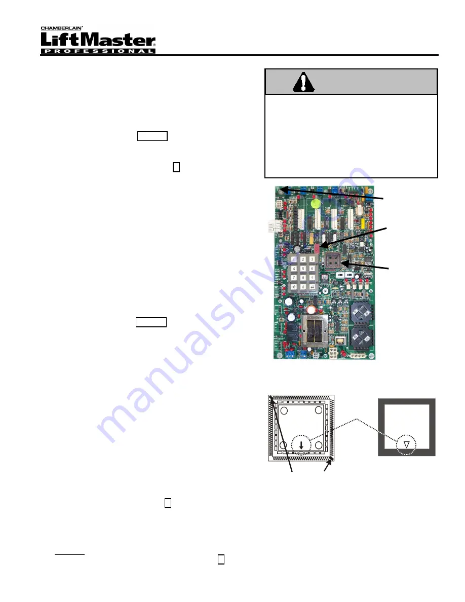
Figure 1: X1 Board
Chip Receptacle
Match arrows
when inserting
new chip.
New X1 Chip
Liftmaster
06-X1-
FID# _______
rev
When removing old chip,
insert chip puller hooks here.
Figure 2: Removing/Inserting the X1 Chip
5
TEST the full functionality of all the
operator’s accessories/inputs (e.g., loops,
photo eyes, etc.). Refer to the operator’s
Installation Instructions
for more information.
6
Replace operator cover (or access door).
To avoid serious BODILY INJURY or damage
to the operator:
TURN OFF power at the power switch
before servicing the operator.
GROUND YOURSELF thoroughly before
handling the circuit board. Grounding
methods include touching a cold, grounded
metallic pipe or using a grounding strap.
WARNING
7-Segment
LED
Chip
Receptacle
Verify Board
Number Here
(SN1110073)