background image

C-9877


Robot with infrared remote control   


Arduino System 


These instructions indicate how to build the same Arduino-type smart robot vehicle. It states how to 

install step by step robot chassis, Arduino compatible motherboard, Shield module, geared motors, battery 
holder and the other accessories as well as their wiring system. 

With this project, you will learn how to program the Arduino system and its learning platform. 
It should be noted that to assemble this kit,

 only a screwdriver is needed, NOT INCLUDED 


included. All electrical and electronic 

parts can be connected or screwed

 into a terminal block or Clema. 

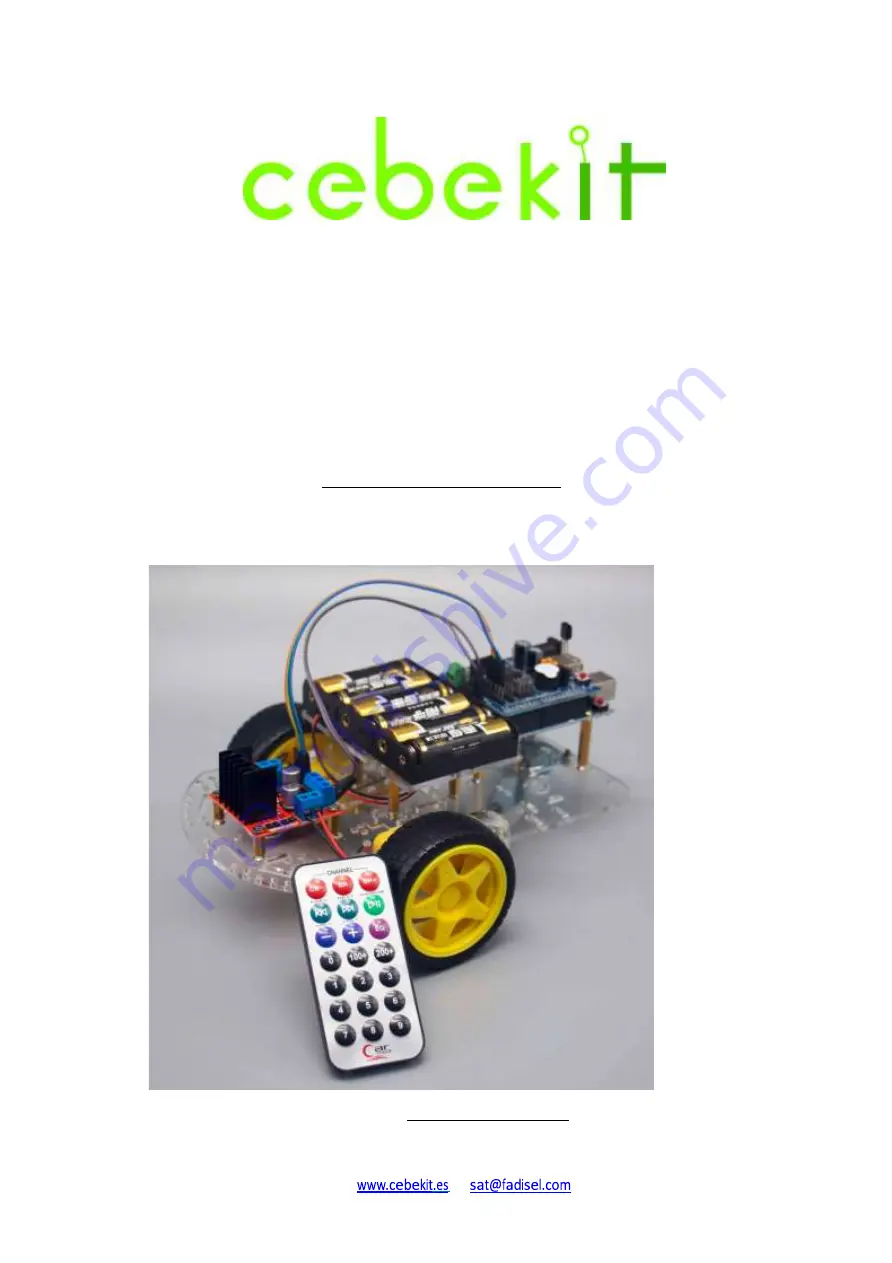
This smart robot can be controlled remotely thanks to its wireless controller, which emits infrared 

light, and the IR receiver built into the vehicle. 

.   


Views of the built robot


Summary of Contents for C-9877

Page 1: ...es as well as their wiring system With this project you will learn how to program the Arduino system and its learning platform It should be noted that to assemble this kit only a screwdriver is needed NOT INCLUDED included All electrical and electronic parts can be connected or screwed into a terminal block or Clema This smart robot can be controlled remotely thanks to its wireless controller whic...

Page 2: ...C 9877 www cebekit es sat fadisel com ...

Page 3: ...ic material 4 18 Screw M3 x 8mm 30 7 Control motors module L298 1 19 Screw M3 x 30 mm 5 8 Robot s Chassis Transparent Acrylic Plastic 3 mm 1 20 Nut M3 12 9 Battery holder s base Acrylic Plastic 3 mm 1 21 Screw M3 x 10 mm 3 10 USB Line Connection cable Robot USB 1 22 Infrared Receiver 1 11 Motor with reduction 1 48 With double axis and cables 2 23 Remote control Infrared Transmitter 1 12 Battery ho...

Page 4: ...ors 4 3 Gearbox motor with double axis and cables 2 4 Wheel Ø65mm with rubber tire 2 5 M3 30 mm screws 4 6 M3 Nuts 10 7 M3 8 mm screws 4 8 Robotic free wheel 1 9 Tool needed Screwdriver 1 Figure 1 1 Necessary pieces for the chassis assembly Before to start the assembly remove the acrylic protection film as it is indicated hereafter Figure 1 2 ...

Page 5: ...ews and nuts to fix motors to the supports Figure 1 4 Pay attention to motors details in order to place them in the correct position Figure 1 5 Motors Installation View from the bottom part of chassis motor side Mark the cables of each motor The red cable is always on the upper part Outgoing element It is recommended to fix the cable with a hot melt adhesive ...

Page 6: ...en from the side of the motors lower side The inverted L shaped groove indicates the correct position Figure 1 7 Insert one of the motor s support from the top of the chassis as shown in the figure Figure 1 8 Now place the motor as shown in Figures 1 4 and 1 5 of the attached picture The outgoing element must always remain on the outside of the chassis Then place the other support inserting it as ...

Page 7: ... it is in abutment with the chassis Figure 1 10 Install the other motor following the same instructions as for the first one In the picture below you can see the correct chassis position indicated by the inverted L shaped groove View of the side of the motors If your chassis is assembled upside down it will necessary to be disassembled and correctly reassembled it see Figure 1 6 ...

Page 8: ...Robotic Free wheel Fix the wheel with M3 8 screws and M3 nuts as it is indicated on following figures Figure 1 11 Holes where must be fixed the wheel Figure 1 12 Wheel in its correct position before its fixing ...

Page 9: ...C 9877 Figure 1 13 Nuts are placed on the lower parts of the chassis Figure 1 14 Insert by pressure the two large wheels on the outer axis of each gearbox motor Bottom view of the chassis ...

Page 10: ...following instructions Firstly First Strongly grasp the two circuit boards as shown in the picture Secondly Carefully separate the two plates by pulling on both circuits Thirdly Be careful not to damage or bend the connector contacts Check one by one that all pins are correctly aligned with the connector s holes in the main board These two points must be checked very carefully to avoid that a shor...

Page 11: ...cuit Arduino Uno Type We will use 1 Smart Robotic chassis with all wheels 1 2 Module Arduino Uno Type 1 3 M3 8 mm Screw 8 4 M3x25 mm Metal spacer 4 5 Necessary tools Screwdriver 1 Figure 2 1 Necessary pieces to install the main control circuit ...

Page 12: ...C 9877 Figure 2 2 Fix the four cylindrical spacer as it is indicated on the figure Figure 2 3 Main control circuit indicating the four fixing points ...

Page 13: ...C 9877 Figure 2 4 Main control circuit fixed with screws ...

Page 14: ...1 Before connecting carefully check the position of the Shield module and the main control circuit connector 2 Check one by one that all the pins are correctly aligned with the holes in the main control circuit connector Check one by one that all the pins are correctly aligned with the holes in the main control circuit connector These two points should be carefully checked to avoid a short circuit...

Page 15: ...ries holder We will use 1 Robot 1 2 Batteries holder 1 3 M3 25 mm Metal spacer 4 4 M3 10 mm screw 10 5 Support acrylic board of the batteries holder 1 6 M3 Nut 2 7 Necessary Tools Screwdriver 1 Figure 4 1 Necessary pieces ...

Page 16: ...C 9877 Figure 4 2 Spacers location Figure 4 3 Acrylic board fixing ...

Page 17: ...C 9877 Figure 4 4 Preparation to fix the batteries holder Figure 4 5 Batteries holder once screwed fixed ...

Page 18: ...t of motors We will use 1 Robot 1 2 Control circuit of motors 1 3 M3 10 mm Metal spacer 4 4 M3 10 mm Screw 4 5 M3 8 mm Screw 4 6 Necessary tools Screwdriver 1 Figure 5 1 Pieces that we will use to fix the control circuit of motors ...

Page 19: ...C 9877 Figure 5 2 Spacers positions Figure 5 3 Control Circuit once fixed ...

Page 20: ... of the Batteries holder Figure 6 1 Batteries holder wiring Batteries holder Circuit Arduino UNO type with the Shield module assembled RED Cable Terminal positive of the terminal block feed BLACK Cable Terminal negative of the terminal block feed ...

Page 21: ... Figure 6 3 Connect the left motor cables to the left side of the motor control module A1 and A2 terminals and those of the right motor to the right side B1 and B2 terminals Motor Motors Control Module Left motor Red cable Output terminal A A2 Left motor Black cable Output terminal A A1 Right motor Red cable Output terminal B B2 Right motor Black cable Output terminal B B1 ...

Page 22: ...C 9877 Step 7 Connection between motors control module and shield module Figure 7 1 Locations of contacts on the shield module Figure 7 2 Connector once connected on the Shield module ...

Page 23: ...C 9877 Figure 7 3 View of the other extremity of the connector connected to the motor control module Pay attention to the polarity Motors control module Shield Module IN1 D8 IN2 D9 IN3 D10 IN4 D11 ...

Page 24: ...nected to the terminal block of the motors control module Figure 7 5 Connection of the power supply to the motors control module Attention polarity The positive pole 12V corresponds to the corner terminal of the motors control module see picture The terminal which is more centered on this terminal block is not used Figure 7 6 The other extremity of the cable has two female connectors that will con...

Page 25: ...gure 7 7 View of the location of the terminals on the Shield module They are indicated on the module as 9V positive and GND negative Figure 7 8 Cable connection on the Shield module Pay attention to the polarity ...

Page 26: ...pletely finished where it is possible to appreciate the power supply connection of the motors control module The colors of the cables may vary depending on the photographed model Motors control Module Shield Module 12V 9V Power Supply GND GN ...

Page 27: ...C 9877 Step 8 Remote control We will use 1 Base robot previously assembled 1 2 Remote control infrared transmitter 1 3 Infrared receiver 1 Figure 8 1 Remote Control LEFT and infrared receiver RIGHT ...

Page 28: ...gure 8 2 Loudspeaker with protection label We will now connect the infrared receiver which is simply connected Figure 8 3 Location of the base where the Figure 8 4 View of the correct position of the infrared receiver must be connected receiver Caution Do not confuse the correct polarity of the infrared receiver ...

Page 29: ...otected with special insulation that you can see on the bottom of the remote control It is necessary to remove this insulation in order to connect the remote control Figure 9 1 Pull the insulation outward until it is off the remote control Keep this insulation Figure 9 2 Remote control prepared for use ...

Page 30: ...ons of the infrared remote control Note The infrared software only accepts 5functions keys Please adjust the software to the values indicated in this instructions manual page Tunr LEFT Turn RIGHT BACKWARD FORWARD PAUSE ...

Page 31: ...duino cc en Main Software and download the suitable software on your computer For it 2 Connect the batteries to the robot 3 Connect the robot to the computer using the USB cable of the kit 4 Install the Arduino Software in the robot 5 Install the software included in this CDROM IRemote proceeding as follows A Open the ARDUINO sofware ...

Page 32: ...C 9877 B Go to PROGRAMA and click C Click on INCLUIR LIBRERIA and then click on AÑADIR LLIBRERIA ZIP ...

Page 33: ...C 9877 D It will open to the directory where the robot files are in supplied CDROM E Select the directory where we are the robot software ...

Page 34: ...en The library will be installed in the ARDUINO software Close the ARDUINO software to save the library Open the Arduino software again and verify that the library is properly installed H Click File and then click EXEMPLES Check in the submenu that the library is well installed ...

Page 35: ... the Shield module The robot buzzer will sound and it will be ready to be used with infrared remote control 10 When you will be sufficiently comfortable with the handling of this robot if you wish you can learn to program with Arduino and or experiment and modify the software at your convenience In case of problems with the new software you only have to install again the software remote_control in...

Page 36: ...C 9877 Diagram of the control board ...

Page 37: ...C 9877 Diagram of the Shield module This is the complete drawing of the Shield module Depending on the selected kit only certain parts of the module will be used ...

Page 38: ...C 9877 Drawing of the motors control module ...

Page 39: ...on Precautions with batteries 1 To place remove or change batteries it is necessary an adult to do this 2 Do not short circuit contacts of the batteries holder or their compartments 3 Remove old batteries from the device to prevent acid leakage 4 Never mix new and used batteries or batteries of different types 5 Never mix alkaline standard coal zinc or rechargeable nickel cadmium Ni MH or other ty...

Reviews: