background image

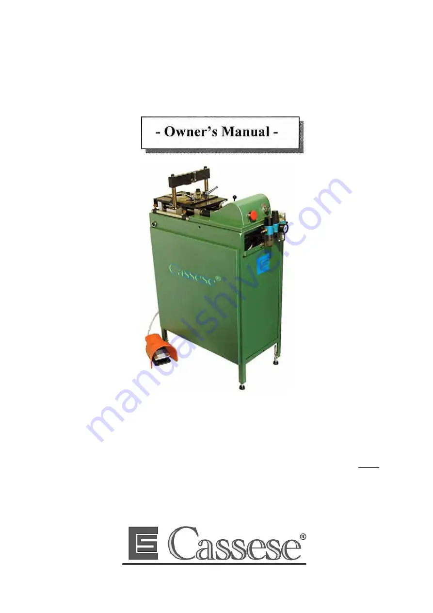
CS 276E Electronic Underpinner

SETTING UP OPERATIONS

In most of cases, your Cassese supplier will set up the machine for you.

If this is not the case, first follow the separate "INSTRUCTIONS FOR SETTING UP
BEFORE OPERATION" (pages A & B)

As long as you are not instructed to do so, do not connect the machine to any air or power
source.

Factory Head office : Zone industricllc - F - 77390 VERNEUIL L'ETANG - FRANCE

Web Site :

www.cassese.com

.

Summary of Contents for CS 276E

Page 1: ...achine for you If this is not the case first follow the separate INSTRUCTIONS FOR SETTING UP BEFORE OPERATION pages A B As long as you are not instructed to do so do not connect the machine to any air or power source Factory Head office Zone industricllc F 77390 VERNEUIL L ETANG FRANCE Web Site www cassese com ...

Page 2: ...ger bracket E towards the keyboard side as much as possible For security in transportation the bracket E is in buttom position 3 Fix also the manometer in the accessory box on the air regulator of the machine To bring up now the plunger bracket E mechanism of the machine 4 Remove the side grey casings of the machine by pulling them upside This way you get access to the inside of the machine You ha...

Page 3: ...the start of travel switch Part C with the screws P paying attention that the button of the switch is upside like in drawing FIG 1 1 11 Now to fix the part B in form of an L you need to bring up the whole mechanism For this push up the whole mechanism from the buttom of the stapling cylinder air piston bring up the mechanism until the part E start of travel stop in form of comes up higher than the...

Page 4: ...nitial wedge insertion can either be at the front or back depending on which arrow indicator is lit Selection of the number of wedges is decided by the keys 1 2 Wedge insertion will start according to the selection of the or key 1 and the position chosen for the arrow key if lights up this indicates that the wedge cartridge is empty If the wedge insertion cycle has not been completed the machine w...

Page 5: ...emove the cartridge from the rear and snap the sliding finger FA under the metal tongue FB Insert the new cartridge from the rear and slide it forwards until the front of the cartridge is underneath the distributor head H Lift the lever HA to release the sliding finger FA Lower the plunger F and retighten the holding screw N B When the cartridge is empty the indicator is illuminated If this occurs...

Page 6: ... Slide the cross bar to the forward position and slide the handle X to the rear and tighten If wedges are being inserted at different levels check by raising the head with the lever HA that no part of the moulding will prevent the distributor head rising to the correct position In order to select the number of wedges press the keys 1 and 2 Key 1 always corresponds to the position where the first w...

Page 7: ...foot pedal One pressure on the foot pedal operates the complete cycle as selected until the clamp releases PUTTING IN THE FENCES See Fig 5 If the joint is open on top rotate both buttons K the same amount towards the minus sign If joint is open at the bottom rotate both buttons K the same amount towards the plus sign ADJUSTMENT OF DRAUGHT ANGLE Fig 5 The draught increases slightly the cut angle of...

Page 8: ... RAZ to restart the machine ADJUSTMENT OF CLAMPS see Fig 6 If when the clamps are operated the left hand moulding is not gripped properly adjust the left hand clamp by unscrewing the knurled knob R on the front of the machine If on the other hand the right hand moulding is loose the clamp can be tightened by screwing in the knurled knob R If the joints are being glued apply the glue before carryin...

Page 9: ...h 90 Lower the cylinder and hammer assembly until the cross bar touches the worktable Undo the screw holding the hammer Remove the hammer to be changed Grease the new hammer and fit carefully into place Insert the locating pin and the hammer holding screw into the hole and tighten the screw sufficiently until the hammer is held against its support Raise the cylinder and hammer assembly so that the...

Page 10: ... to time remove the distributor head H and clean all the area in contact with the front of the wedge cartridge with a stiff brush used dry Service and greasing If movement becomes sticky oil the horizontal bars use 20 20 SAE oil Cleaning Do not use any wet materials to remove excess glue that has collected on the machine It helps to remove the glues if the area is sprayed with a silicone grease pr...

Page 11: ...imum distance between the bung and the moulding is incorrect 45mm Max The stopping microswitch is out of adjustment page 6 check the position of the bung fig 4 check that the air pressure is a minimum 5 bars If the speed of the descent of the bung is too slow make the necessary adjustment A foreign body is preventing the hammer rising completely Check the area around the hammer support Blockage re...

Reviews: