


© 2014, Carmanah Technologies Corporation. June 2014. 61249_M650H_User_Manual_RevC
USER MANUAL
Technical Support:
Email: [email protected]
Toll Free: 1.877.722.8877 (US & Canada)
Worldwide: 1.250.380.0052
Fax: 1.250.380.0062
Web: carmanah.com
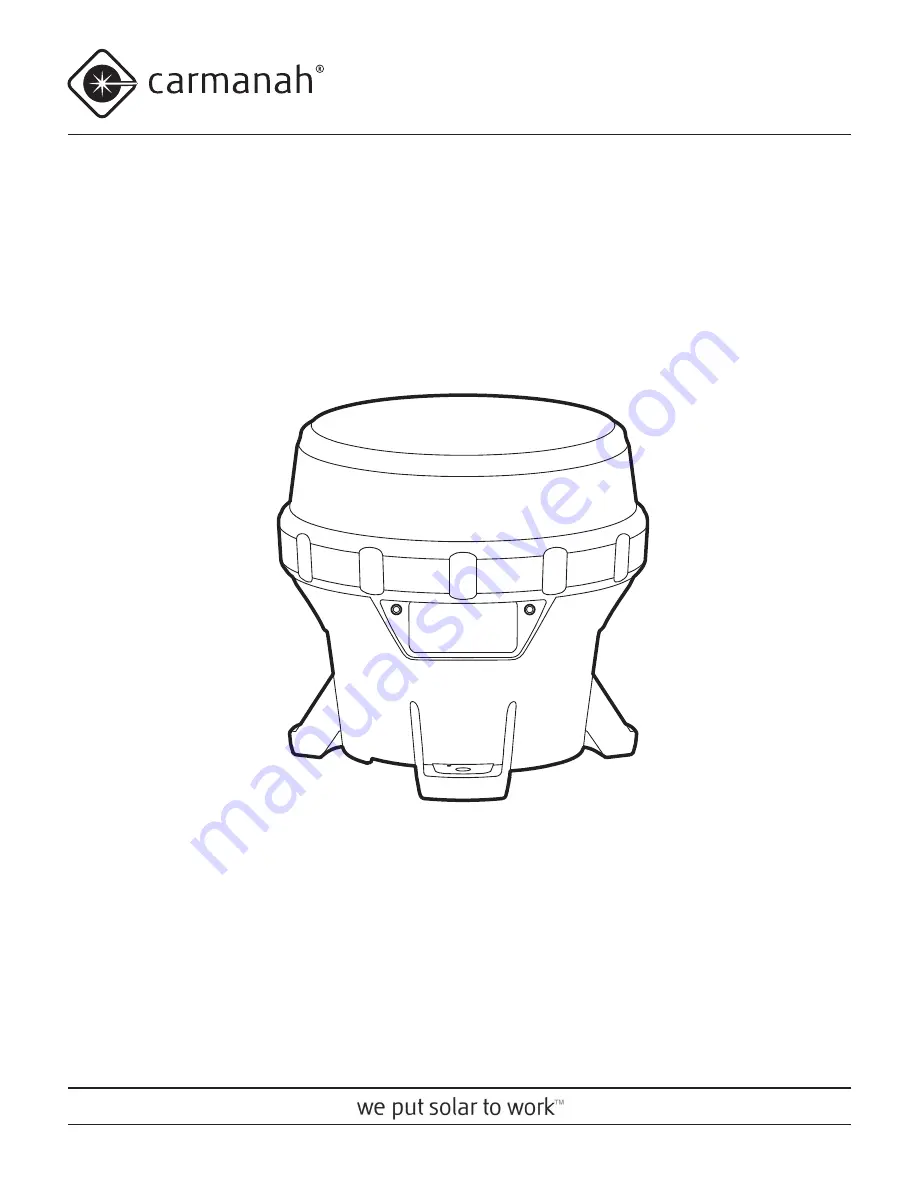
M650H
The Carmanah M650H User Manual is your essential guide to maximize the potential of this innovative product. Packed with detailed instructions, diagrams, and tips, this manual is a valuable resource for all users. Download it for free from our website to unlock the full potential of your Carmanah M650H device.
© 2014, Carmanah Technologies Corporation. June 2014. 61249_M650H_User_Manual_RevC
USER MANUAL
Technical Support:
Email: [email protected]
Toll Free: 1.877.722.8877 (US & Canada)
Worldwide: 1.250.380.0052
Fax: 1.250.380.0062
Web: carmanah.com
M650H


