Mounting
Hang the device to the DIN-Rail being sure that
the spring closes. Use a screwdriver to remove
the product
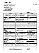
Connections
DPB01
PPB01
Adjustment
Yellow
Relay output status
Red
Alarm status
Green
Device ON
Undervoltage
Overvoltage
Delay
Check if the input range is correct. Turn the power ON. The green LED is ON. Adjust the delay, upper ( ) and lower ( ) level knobs to the desired value.
Provided that all the 3 phases are present in the proper sequence, as long as they are all within upper and lower set points, relay and yellow LED are
ON. When one or more phase exceeds the upper level or drops below the lower level for more than the set delay time relay and yellow LED turn OFF,
red LED (flashing 2 Hz during the delay time) turns ON. If the phase sequence is wrong or one phase is lost the output relay releases immediately (only
200 ms delay occurs). This failure is indicated by the red LED which flashes 5 Hz as long as the alarm condition is occurring.
Installation instructions
TRMS 3-phase voltage monitoring relay
D/P PB01CM23/N
D/P PB01CM44
D/P PB01CM48/N
Code 8022250/071022 INSTRUCTION SHEET
XPB01/XPB01N V8
www.gavazziautomation.com
Scan to read me in your language!
Scannen Sie, um mich in Ihrer Sprache zu
lesen!
Scanne pour me lire dans ta langue !
¡Escanea para leerme en tu idioma!
Scansiona per leggermi nella tua lingua!
Scan for at læse mig på dit sprog!
扫码后选择相关语言进行阅读!
SW1
ON: 6 s
OFF: 1 s
SW2
ON: 3P+N
OFF: 3P
CM23, CM48
CM44
Settings
SW1:
Power ON delay
SW2:
Mains type
SW3-SW4-SW5:
Nominal voltage
SW6:
Not used
(M23, M48)
SW3
ON
ON
OFF
OFF
SW4
ON
OFF
ON
OFF
M23 Ph-Ph 208 V 220 V 230 V 240 V
M23 Ph-N 120 V 127 V 133 V 140 V
M48 Ph-Ph 380 V 400 V 415 V 480 V
M48 Ph-N 220 V 230 V 240 V 277 V
(M44)
SW3
ON
ON
ON
ON
OFF
OFF
OFF
OFF
SW4
ON
ON
OFF
OFF
ON
ON
OFF
OFF
SW5
ON
OFF
ON
OFF
ON
OFF
ON
OFF
M44 Ph-Ph 208 V 220 V 230 V 240 V 380 V 400 V 415 V 480 V
M44 Ph-N 120 V 127 V 133 V 140 V 220 V 230 V 240 V 277 V
To access the DIP switches open the plastic cover using a screwdriver as shown on the left.
Select the input voltage range by setting DIP switches 3 and 4 for M23 and M48 versions, DIP switches 3, 4 and 5 for M44 only. Select the desired
function by setting DIP switches 1 and 2. Use DIP switch 1 to set a power ON delay. The actual mains reading will start after this set delay, thus alarms
are inhibited during the delay. DIP Switch 2 sets the mains as either 3Ph (Delta) or 3Ph + N (Star).
Do not open the DIP switches cover if the power supply is ON
DPB01
PPB01
Terminals
Tightening torque
(DPB01)
L1, L2, L3, N 5, 6, 7, 11
Power supply
15, 16, 18
1, 3, 4
Relay output
DPB01
: each terminal can accept up to 2 x 2.5 mm
2
wires
Connect the 3-phase power supply and the neutral (if present) taking care of the sequence (N ver-
sions don’t detect incorrect phase sequence). Connect the relay output according to the ratings.
Keep power OFF while connecting!
Packaging
The packing material should be kept for redeliv-
ery in case of replacement or repair.
CE-marking and approvals