Carel humiSteam Basic UE003, Installation Operation User Manual
The Carel humiSteam Basic UE003 is an advanced humidification system designed for efficient and effective humidity control in various applications. Ensure a hassle-free installation and operation with the comprehensive Installation Operation User Manual, available for download for free from our website. Explore the full potential of this product today!
Share
Download


Reviews:
No comments
Related manuals for humiSteam Basic UE003

BD22MWSA
Brand: Black+Decker Pages: 64

40S MKII
Brand: Dantherm Pages: 292

EDV-2200
Brand: Eva-Dry Pages: 6

HL-OS-10
Brand: Haus & Luft Pages: 44

447400HB
Brand: Aircare Pages: 33

36316
Brand: Hunter Pages: 11

R-9916
Brand: Rohnson Pages: 15

CM330A
Brand: Aircare Pages: 24

REFLECTION HUL900 Series
Brand: Honeywell Pages: 17
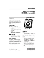
H8908B Humidistat
Brand: Honeywell Pages: 8

HWM845 series
Brand: Honeywell Pages: 18

REFLECTION HUL900BC
Brand: Honeywell Pages: 29
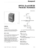
HP970A
Brand: Honeywell Pages: 10
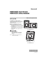
H8908A/B
Brand: Honeywell Pages: 16

TrueSTEAM
Brand: Honeywell Pages: 52

TRADELINE HE360
Brand: Honeywell Pages: 40

HWM 335 - 3G Warm Humidifier
Brand: Honeywell Pages: 44

TrueEASE HE100
Brand: Honeywell Pages: 32


