Carad Humifix 10, Service Manual
The Carad Humifix 10 Service Manual is a comprehensive and detailed guide designed to assist you in maintaining and troubleshooting your Humifix 10 model. This user-friendly manual is available for free download on our website, ensuring that you have quick and easy access to all the information and instructions you need.
Share
Download


Reviews:
No comments
Related manuals for Humifix 10
ZD30
Brand: Zenith Pages: 6
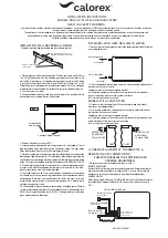
DH30A
Brand: Calorex Pages: 15

DH44 Series
Brand: Calorex Pages: 20

40S MKII
Brand: Dantherm Pages: 292

NSUH-342
Brand: NScessity Pages: 4

FT-F Series
Brand: UCAN Pages: 20

HU1052
Brand: SOLAC Pages: 4

EVAP3
Brand: Vornado Pages: 18

MEDIBREEZE
Brand: Medisana Pages: 66

Indurre IND-600
Brand: KAF International Pages: 7

HMA/Z 270
Brand: HIdRos Pages: 56

HU3000 Series
Brand: Philips Pages: 2

BiPAP AVAPS
Brand: Philips Pages: 8

HU2510/00
Brand: Philips Pages: 11

HU2510
Brand: Philips Pages: 15

HU2000 Series
Brand: Philips Pages: 16

DreamStation Auto CPAP
Brand: Philips Pages: 32

DreamStation 2
Brand: Philips Pages: 68


