


CALIFORNIA ACCENT LIGHTING, INC.
2034 E. Lincoln Ave. #431, Anaheim, CA 92806
ph. 800.921.CALI (2254) or 714.535-7900 \ fx. 714.535.7902
[email protected] \ calilighting.com
© CALI. All rights reserved. CALI reserves the right to make changes or withdraw specifications without prior notice.
Installation Instructions
Overview
LLED
8700-OL
1 of 12
lip
LEDs
™
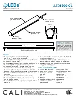
Frosted Lens Cover
(#LLED8700-OL-LF)
End Cap
(#LLED8700-OL-EC)
Aluminum Extrusion
(#LLED8700-OL)
Power Connector
(#LLED8700-PC)
End View
1.20”
1.46”
1.20”
1.46”
INSTALLATION TOOLS REQUIRED
WARNING
• Do not power lipLEDs when coiled or bunched together.
Maintain half inch spacing between parts when lit
• Do not cover lipLEDs as the covering may cause it to overheat, melt, or ignite
• Do not puncture or damage lipLEDs
• Do not route lipLEDs through walls, doors, windows, or building structures
• Do not roll out lipLEDs on rough surfaces or over sharp corners.
• Do not use lipLEDs if damaged, such as, broken outer jacket, loose
connections, or frayed wire insulation. Inspect periodically
• Do not secure lipLEDs with staples, nails, or like means that might
damage the insulation. Secure using mounting clips or mounting channel
• Do not submerge lipLEDs in liquid or install near standing water or
other liquids
• Do not install lipLEDs where it is subject to continuous flexing
• Do not mount lipLEDs inside cabinets, tanks, or enclosures of any
kind without proper ventilation
• Do not run lipLEDs at an operation temperature exceeding 65C or 149F or
below -20C or -4F
• Use only standard outdoor extensions cords, such as, SW, STW, STOW,
SJW, SJOW, SJTW, and SJTOW
• Ground Fault Circuit Interruptor (GFCI) protection is required on
circuits or outlets when lipLEDs is used for outdoor applications
• Surge protector must be set up for electrical power system to avoid
damaging lipLEDs lighting system
• Electric Compound Miter Saw
• 14.4 to 28 Volt Cordless Drill
• Wire Strippers for 22 and 15
gauge wire
• Pliers
• Wire Cutter
• Phillips Bits - Sufficient Quantity
• Carbide Masonry Drill Bits -
Sufficient Quantity
• Concrete Tapcon Screws
• Self Drill Metal Screws #4 x 1/2”
- Sufficient Quantity
• Electrical Cords
• Electrical Three Way
• Safety Glasses
• Measuring Tape
• Marker
• Chalk Line
IMPORTANT
VERIFY CORRECT
LUMINAIRE WAS RECEIVED WITH
CORRECT COLOR TEMPERATURE
AND VOLTAGE BEFORE CUTTING
OR INSTALLING.
CALI
WILL NOT
BE RESPONSIBLE IF INCORRECT
LUMINAIRE IS INSTALLED.
2” increments up to max run
± 0.125” cutting tolerance
*See max run for more information
2”
6” increments up to max run
*See max run for more information
6”
2” increments up to max run
± 0.125” cutting tolerance
*See max run for more information
(Run lengths required)
2”
3.9” or 6.5”
6.5”
2” increments up to max run
± 0.125” cutting tolerance
*See max run for more information
2”
8’ Maximum extrusion and lens length
8’ Maximum extrusion and lens length
(Dry Location field cuttable)
Lens and extrusion shipped in
8’ sections (field cuttable)
8’ Maximum extrusion and lens length
3.95” increments up to max run
± 0.125” cutting tolerance
*See max run for more information
3.95”
LLED8400 --->
LLED8000 --->
LLED8200 --->
LLED8300 --->
LLED8500 --->
LLED8100 --->
Specify Length (19.7”Assembly Increments)
(Add 2.5” to run for end cap and strain relief)
.75”
5.5W
.78”
.52”
*1.5W, 2.5W,
3.6W, 4.5W
.47”
.36”
6.5” (2.5W) or 3.9” (5.5W) increments up to max run
± 0.125” cutting tolerance
*See max run for more information
6.5“ increments up to max run
± 0.125” cutting tolerance
*See max run for more information
2” increments up to max run
± 0.125” cutting tolerance
*See max run for more information
2”
6” increments up to max run
*See max run for more information
6”
2” increments up to max run
± 0.125” cutting tolerance
*See max run for more information
(Run lengths required)
2”
3.9” or 6.5”
6.5”
2” increments up to max run
± 0.125” cutting tolerance
*See max run for more information
2”
8’ Maximum extrusion and lens length
8’ Maximum extrusion and lens length
(Dry Location field cuttable)
Lens and extrusion shipped in
8’ sections (field cuttable)
8’ Maximum extrusion and lens length
3.95” increments up to max run
± 0.125” cutting tolerance
*See max run for more information
3.95”
LLED8400 --->
LLED8000 --->
LLED8200 --->
LLED8300 --->
LLED8500 --->
LLED8100 --->
Specify Length (19.7”Assembly Increments)
(Add 2.5” to run for end cap and strain relief)
.75”
5.5W
.78”
.52”
*1.5W, 2.5W,
3.6W, 4.5W
.47”
.36”
6.5” (2.5W) or 3.9” (5.5W) increments up to max run
± 0.125” cutting tolerance
*See max run for more information
6.5“ increments up to max run
± 0.125” cutting tolerance
*See max run for more information


