BWT 3 x 3, Installation And Operating Intructions
Get your hands on the comprehensive Installation and Operating Instructions manual for the cutting-edge BWT 3 x 3 product. Available for free download, this manual provides step-by-step guidance for effortless setup and efficient operation. Get all the details you need from manualshive.com, ensuring a seamless user experience with your BWT 3 x 3.
Share
Download


Reviews:
No comments
Related manuals for 3 x 3
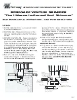
RENEGADE
Brand: Waterway Pages: 2

SILENSOR PRO SP200BTP
Brand: Davey Pages: 24

NT6122
Brand: Blue Wave Pages: 4

18W/12V
Brand: Albixon Pages: 8

290732 Series
Brand: avenli Pages: 67

SFP6-21-CZ
Brand: avenli Pages: 67

Prowler 720
Brand: Pentair Pages: 2

AutoChlor SM30
Brand: AIS Pages: 4

Clean Active
Brand: Fiap Pages: 28

56451
Brand: Intex Pages: 12

COSMY THE BOT 100
Brand: BTW Pages: 32

MVAC
Brand: Pond Boss Pages: 20

OCTO+ PRO
Brand: Procopi Pages: 36

TopClean II
Brand: JBL Pages: 8

HYDROCHLOR TS 20 SC
Brand: Waterco Pages: 6

StarFlo DSF150CE
Brand: Davey Pages: 84

E.SWIM
Brand: DAB Pages: 33

Skimmer Filter MK II
Brand: Aquatic Lifestyles Pages: 4


