background image

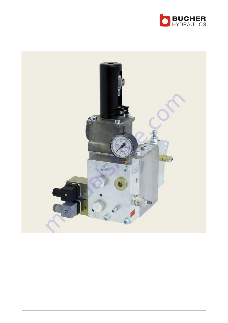
C−LRV Lift Control Valve, Size 175 / 350 / 700

NTA−2 power supply unit and C−DELCON

Issue: 08.08

Installation and startup guide

1/92

Classification: 450.500.500  

Reference: 300−I−9010212−E−10/08.08

Summary of Contents for C-LRV 175

Page 1: ...C LRV Lift Control Valve Size 175 350 700 NTA 2 power supply unit and C DELCON Issue 08 08 Installation and startup guide 1 92 Classification 450 500 500 Reference 300 I 9010212 E 10 08 08...

Page 2: ...Hydraulics AG Data is provided for the purpose of product description only and must not be construed as war ranted characteristics in the legal sense No assertion regarding either a particular propert...

Page 3: ...p 18 1 4 C DELCON electronic card 20 1 4 1 Factory settings 20 1 4 2 Description of function 21 1 4 3 Technical data 22 1 4 4 Travel and switching diagram for normal travel distance 23 1 4 5 Travel an...

Page 4: ...oor zone SIU 4 57 4 3 7 The inspection travel speed setting 57 4 3 8 Positioning the shaft switches for the deceleration distance 58 4 3 9 Required deceleration distance 59 4 3 10 Setting the mechanic...

Page 5: ...use in all phases of operation and is valid for all model series that are referred to 0 1 Target group S Operator S Installer S Service engineer S Repair technician 0 2 Supplementary documents Descri...

Page 6: ...C LRV lift control valve 6 92 300 I 9010212 E 10 08 08...

Page 7: ...ion 7 92 300 I 9010212 E 10 08 08 0 1 Product description 1 1 Important notes 1 1 1 Subassemblies This guide differentiates between the following subassemblies C LRV lift control valve C DELCON electr...

Page 8: ...erating hydraulically driven passenger and goods lifts The products must not be handled in any way by unauthorised persons 1 1 3 Conformity The product was designed and developed in conformity with th...

Page 9: ...150 21 45 R 250 K 251 6 80 55 bar 1 Valve type C LRV 175 2 Flow rate UP 120 l min 3 Flow rate DOWN 150 l min 4 Minimum static pressure empty car 21 bar 5 Maximum static pressure full car 45 bar 6 Flo...

Page 10: ...15 45 l min R 45 46 90 l min R 90 91 250 l min R 250 C LRV 350 251 500 l min R 500 C LRV 700 400 1000 l min R 1000 R 250 K 251 VN D0 C LRV 175 Spool flow rate type C LRV 175 15 90 l min K 91 91 250 l...

Page 11: ...ot filter Test point G Pressure gauge Pressure gauge shut off screw Air bleed screw Feedback sensor Main filter 12 13 14 15 16 17 18 20 22 Flow rate measuring system Emergency lowering valve DOWN spoo...

Page 12: ...contacting Main filter Flow rate measuring system Emergency lowering valve 14 15 16 20 21 22 23 24 DOWN spool Check valve UP spool Pipe rupture valve Ball valve Electrical emergency lowering valve op...

Page 13: ...n The lift control valve can be subdivided into 3 main functions 1 Up section pressure relief valve 4 16 1 S Initial position UP spool 16 is open in the 0 position pump flow goes directly to tank S Up...

Page 14: ...DOWN spool 14 is progressively opened by the electro proportional valve DOWN solenoid this results in smooth acceleration S Deceleration DOWN spool 14 is progressively closed by the electro proportion...

Page 15: ...The baffle disc is displaced axially as a function of the flow rate S This axial displacement is converted by a non contacting feedback transducer 10 into an electrical DC signal the feedback signal...

Page 16: ...0015573 H R L a A Legend 1 2 3 4 Flow rate measuring system Pressure relief valve DOWN solenoid UP solenoid 5 6 7 a View A Z1 Z2 Z3 P T Z Pressure switch port Pressure switch port Hand pump port Pump...

Page 17: ...5 15 M8 9 23 C LRV 350 219 355 190 207 65 48 63 200 35 38 85 25 M10 14 28 C LRV 700 297 428 255 225 80 87 83 265 48 56 124 41 M10 30 30 Type Flow range Spool K Viscosity range Max oil temperature Q l...

Page 18: ...0 20 50 90 100 150 180 200 250 R45 R90 R250 Spool K 91 Spool K 251 A B Flow ring R DOWN Z T UP P Z DOWN Z T UP P Z C LRV 350 0 0 2 5 5 0 7 5 10 0 12 5 15 0 250 275 300 325 350 375 400 425 450 475 500...

Page 19: ...9010212 E 10 08 08 0 2 5 5 7 5 10 12 5 15 400 450 500 550 600 650 700 750 800 850 900 950 1000 R1000 C LRV 700 A B Flow ring R Spool K 1001 DOWN Z T UP P Z Legend A B Pressure drop bar Min required dy...

Page 20: ...keep the DELCON in its ESD protective bag and only hold it by the spacer studs 4 300 2 10012279 6 1 2 3 5 4 Legend 1 2 3 4 5 6 Nameplate Label with Test number Label with description of LED functions...

Page 21: ...be set through contact K5 of the lift control system there is no SIU 1 monitoring during inspection speed with K5 S Reduced speeds for short travel distances are also possible via K6 K8 S The C DELCON...

Page 22: ...or the C LRV valve S Conforms to the European format 100 mm x 160 mm S Enhanced ride comfort S Automatic reduction of demand signal if nominal speed is not at tained S Extended functions S Simple set...

Page 23: ...nce Y N motor run on time of 0 5 1 s Drop out delay of 0 5 1 s Y Y starting time of up to approx 3 s with Y K1 and K2 not until connection Legend 1 2 3 4 Motor contactor ON Safety relay R2 closed K2 S...

Page 24: ...istance between floors with normal speed slow speed travel distance too long Short distance between floors with reduced speed K6 N K N K Z X Z Y Z Y X Z Y V Motor run on time of 0 5 1 s Drop out delay...

Page 25: ...between 20 100 of nominal speed S Speed can be set by means of parameter K6 speed or K7 speed K8 speed in the Options menu to match the floor spacing distance between stops S Acceleration can be adju...

Page 26: ...wer supply and physical support for the C DELCON 300 1 10008856 Legend 1 2 3 4 5 Mains voltage terminals Socket for feedback cable Terminal block screwless Jumper JP2 connects Earth and Signal GND Ter...

Page 27: ...g 0 3 m s in the door zone 1 4 SIU 1 and SIU 4 active functions as above Parameter Relay function only SIU all errors The relay on the power supply unit switches only when there is an SIU fault The r...

Page 28: ...NTA 2 115 100 110 115 120 VAC NTA 2 230 220 230 240 VAC 10 NTA 2 400 380 400 415 440 VAC Frequency 50 60 Hz 10 Power consumption 20 W during travel approx 8 W at standstill EMC standards EN 50081 EN 5...

Page 29: ...Connection for feedback cable Mains voltage connection D E Demand feedback monitoring Emergency power supply Terminal Description Mains Voltage Connection NTA 2 115 NTA 2 230 NTA 2 400 N L1 Neutral N...

Page 30: ...ential GND for command inputs K1 K8 Ground reference potential GND for command inputs K1 K8 Common DOWN solenoid Output DOWN solenoid Common UP solenoid Output UP solenoid Demand feedback monitoring 1...

Page 31: ...cable break kink etc can endanger trouble free operation It is essential that connection 2 is ground bonded to terminal 12 other wise the null point of the sensor will not be stable If you cut the cab...

Page 32: ...in the surroundings Surroundings Requirement Machine room tempera ture 2 40 C Oil temperature 2 60 C Relative air humidity max 90 non condensing 1 8 Emissions The following emissions can occur during...

Page 33: ...it is not prevented the pro duct or its surroundings may be damaged Caution Denotes a potentially dangerous situation If it is not prevented it may result in slight or minor injuries to people Warnin...

Page 34: ...C LRV lift control valve Safety information 34 92 300 I 9010212 E 10 08 08...

Page 35: ...Allen key 4 mm A F 2 Bypass pressure setscrew Screw Open ended spanner 10 A F mm Allen key 5 mm A F 8 Pressure gauge shut off screw Allen key 4 mm A F 9 Filter screw UP Open ended spanner 22 A F mm 1...

Page 36: ...ating the emergency lowering valve make sure that there are no people or materials in the lift shaft 3 2 Display of the operating status Legend for the LEDs 1 RUN Ready for operation green Lights when...

Page 37: ...o next parameter Increases the value of the current parameter Decreases the value of the current parameter General description S Easy set up of the travel curve S Command feedback value and control vo...

Page 38: ...or key save the value and return to parameter selection S With keys 1 2 3 or 4 do not save the value and return to parameter isation mode S If no key pressed within 5 minutes the DELCON automatically...

Page 39: ...the key decrease it with the key S With or key change to the adjacent number S Press and keys simultaneously to save the number If a password has been set the user must login in order to change para m...

Page 40: ...and 1 command is present S 2nd line existing control voltage C and feedback value F in volts e g Fast speed 7 50 V Display during parameterisation S 1st line parameter name S 2nd line value of paramet...

Page 41: ...ownloaded free of charge from http www bucherhydraulics com 3 4 1 General description Parameterisation S C DELCON parameters can be read off and set via PC S Parameter sets can be saved S Comments can...

Page 42: ...ur computer carry out the following steps before installing the new version 1 Start the old version of WinDelta32 2 In the Options Configuration menu open the Serial Port page I Note the COM port disp...

Page 43: ...ents an installation dialog will be displayed 3 Click the button Next or Install Finish until the installation is ter minated A shortcut will automatically be placed on the desktop Configuring WinDelt...

Page 44: ...file e g the file Para_LRV prm from the folder C Temp 2 Click the button Refresh data 3 Close the window 4 Select the menu Parameters VF LRV and import click Import All parameter sets the stored file...

Page 45: ...ift control valve Operating controls and indicators 45 92 300 I 9010212 E 10 08 08 3 4 4 Connect DELCON to PC Laptop Possibilities for connecting DELCON to PC Laptop Never connect DELCON to an Etherne...

Page 46: ...V lift control valve Operating controls and indicators 46 92 300 I 9010212 E 10 08 08 Connecting to serial port using Bucher adaptor Connecting to USB port using a USB RS232 converter with Bucher adap...

Page 47: ...ss the hose is first disconnected Reorienting the ball valve outlet 1 Unscrew cap screws on head of valve 2 Remove the screws Attention Risk of damage to the flow rate When orienting the ball valve ou...

Page 48: ...TA 2 power supply unit must be installed in the control system cabinet S There must be no voltage at the power supply unit when working on its connections or exchanging the C DELCON Important Set jump...

Page 49: ...ND test measurement 24 V emergency power supply 24 V emergency power supply When contact K5 closes the C DELCON s two fast speeds drop to a preset percentage of their nominal values The setting is adj...

Page 50: ...als 12 19 and 20 S Relay RN drops out when there is a power failure and the two nor mally closed contacts RN 1 and RN 2 connect to the battery I Inputs 19 and 20 have diode protection from polarity re...

Page 51: ...rgency the lift car can be lowered by operating the emergency lowering valve electrically Depending on the external battery voltage 12V and 24V spool valve versions are available Wiring diagram 12 24...

Page 52: ...need for resetting 4 3 2 Checking the minimum static pressure To check the minimum static pressure with empty car 1 Open pressure gauge shut off valve 2 Read the minimum static pressure on the pressu...

Page 53: ...w bypass pressure setscrew 2 approx 2 turns counterclockwise 5 Connect the Handterminal to the C DELCON and press key 3 on Handterminal null point or feedback value will be displayed 6 Send UP command...

Page 54: ...the valve I Page 36 Section 3 1 5 Remove the UP solenoid plug 10 6 Slacken the locknut for bypass pressure setscrew 2 7 Unscrew bypass pressure setscrew 2 approx 2 turns counterclockwise 8 Send UP com...

Page 55: ...cknut for bypass pressure setscrew 2 4 Unscrew bypass pressure setscrew 2 approx 2 turns counterclockwise 5 Send UP command 6 With motor running slowly turn bypass pressure setscrew 2 clockwise until...

Page 56: ...ure is reached 9 Tighten locknut for screw 1 10 Cancel the UP command 11 Write new settings on the existing rating plate overwrite old values I Page 9 Section 1 2 1 Item 5 12 Remove the bypass from th...

Page 57: ...in the door zone and during relevelling If the speed setting is exceeded the lift is stopped per EN 81 2 max 0 3 m s S When the speed setting is exceeded the relay activates S The speed can be set wit...

Page 58: ...shaft switches depends on the car speed 4 3 9 v 50 v 50 v 100 v 100 Aux speed e g Time t X Z Y Z Y Z Z X X Deceleration distance shaft switches for maximum speed Y Deceleration distance shaft switches...

Page 59: ...irect 1 1 drive e g v 0 4 m s x1 0 4 m 2 Deceleration distance X for indirect 2 1 drive e g v 0 63 m s x2 0 71 m 3 Deceleration distance Y for direct 1 1 drive auxiliary speed e g v 0 4 m s 2 0 2 m s...

Page 60: ...displayed 3 Using a 3 mm Allen key slacken the adjusting clamp screw 14 a little 4 Remove Allen key it has a magnetic influence 5 Hold the feedback sensor by the plug and move it axially until the fee...

Page 61: ...alve filter This can cause leakage Never operate the lift without the pilot filter installed Carry out regular maintenance as per maintenance plan Page 89 Cleaning the pilot filter 1 Switch main switc...

Page 62: ...ake sure that there are no people or materials in the lift shaft Attention Uncontrolled descent free fall Can cause damage to the support frame and car The elevator car must come to rest within 3 5 me...

Page 63: ...alue is displayed If the DOWN command is still present on quitting the menu travel will resume normally Important after the pipe rupture valve has closed pressure can again build up between the C LRV...

Page 64: ...an again build up between the C LRV and the pipe rupture valve causing the pipe rupture valve to re open If the pipe rupture valve is to remain closed for a long period this pressure must be vented th...

Page 65: ...rd 4 Error Deceleration Deceleration Accel Inspection Delete errors 5 Error Slow speed Slow speed Inspection speed Pipe rupture 6 Error Soft stop Soft stop Decel inspection 7 Error Relevelling Relevel...

Page 66: ...7 Start speed Acceleration Fast speed Deceleration Slow speed Soft Stop steepness Minimum pressure offset sol 8 9 Demand signal Control voltage prop sol 5 1 3 Overview of control parameters PID Dynami...

Page 67: ...e UP S Operative during Up travel S Higher value higher solenoid starting voltage shorter starting time S Setting range 5 0 100 0 bar S Standard 20 0 bar Important high settings may cause a start up j...

Page 68: ...el S Higher value faster travel speed S Setting range 0 20 2 50 V S Standard 0 40 V Important low settings for Slow speed may cause slow travel to be uneven due to static friction in the cylinder and...

Page 69: ...P sol static S Operative in steady state control processes constant speed travel S Higher value higher solenoid control gain S Setting range 0 20 1 50 S Standard UP 0 80 DOWN 0 70 Important high sett...

Page 70: ...P 0 80 DOWN 0 70 Important high settings may cause oscillations Setting I sol dynamic S Operative in dynamic control processes acceleration deceleration S Higher value longer solenoid reset time great...

Page 71: ...difference is exceeded then Lift is stopped with emergency stop deceleration The relay switches 1 5 1 LED SIU 1 lights If the Relay function setting is only SIU reset operation after there is no longe...

Page 72: ...eed in door zone Dem value Fast UP Setting Accel inspection S Only operative with inspection speed K5 S Higher value greater acceleration i e shorter acceleration distance S Setting range 0 30 5 00 V...

Page 73: ...Standard K8 40 Important only operative with fast travel speed Setting K6 K7 K8 deceleration S Only operative with auxiliary speeds K6 K7 K8 S Higher value greater deceleration i e shorter decelerati...

Page 74: ...unctions Off Few sensitivity Normal Sensitive Setting Start delay S Pause between command and start of travel S Higher value longer pause S Setting range 0 1 1 0 s S Standard 0 1 s Setting Relay funct...

Page 75: ...1 0 1 1 1 1 0 1 1 Insp speed 1 0 0 0 1 1 0 0 0 1 1 0 0 1 1 0 0 1 1 V K6 1 0 0 0 0 1 1 0 0 0 0 1 1 0 1 1 1 0 0 0 1 1 V K7 1 0 0 0 0 0 1 1 0 0 0 0 0 1 1 1 0 1 1 0 0 0 0 1 1 V K8 0 0 0 0 0 0 1 0 0 0 0 0...

Page 76: ...parameter S Overwrites the current parameters with the internally saved parameters S Possible parameter sets Factory factory settings User Command Save parameter S Saves the current C DELCON paramete...

Page 77: ...ersion S Example 2 030 Serial number S Serial number of the C DELCON S Format year month sequential number S Example 0510 09489 Check number S Valve test number S Format year month sequential number S...

Page 78: ...1 3 million Important Relevelling Down operations are not counted Operation hour S C DELCON operating hours counter S Max 65535 hrs unstab voltage Positive unstabilised voltage from the power supply u...

Page 79: ...90 91 250 R 45 R 90 R 250 1 V 4 8 l min 1 V 9 7 l min 1 V 29 1 l min C LRV 350 251 500 R 500 1 V 52 2 l min C LRV 700 400 1000 R 1000 1 V 112 0 l min C LRV 175 120 150 21 45 R 250 K 251 6 80 55 bar C...

Page 80: ...U 1 on C DEL CON lights up S Check mechanical null point 60 4 3 10 S DOWN solenoid is energised S Correct the wiring fault S NTA 2 terminals 7 8 crossed 49 4 2 3 S UP pilot filter dirty S Clean filter...

Page 81: ...rt S Increase deceleration in C DELCON S Bypass pressure set too high S Reset it No DOWN travel S Car overloaded pressure switch has activated S Reduce the load S Contacts K3 K4 and or R1 not closed S...

Page 82: ...out a delay S Set as per page s 23 1 4 4 Car overshoots landing during DOWN travel S Deceleration time too short S Increase deceleration in C DELCON S Deceleration switches in shaft wrongly positioned...

Page 83: ...S Exchange DOWN pilot valve S Emergency lowering valve leaking S Operate it several times during UP command 36 3 1 S Check valve is leaking S Replace seal 11 1 3 S Pressure falls rapidly S DOWN spool...

Page 84: ...monitoring LED lights up S The C DELCON settings are too low S Acceleration is too high S Decrease the acceleration setting S Fast DOWN is set too high on the C DELCON S Decrease the fast DOWN settin...

Page 85: ...gency lowering valve actu ated S Reset the mechanical null point S Set the bypass screw on the valve correctly unscrew it slightly Err Unknown Unknown fault S Internal software fault S Upgrade reinsta...

Page 86: ...1 401 S Hand pump activated S Bypass pressure is too high S Set the bypass screw on the valve correctly unscrew it slightly 103 105 301 401 Warn Leakage Automatic null point adjustment outside of 0 20...

Page 87: ...1 Travel is disabled 202 Travel is aborted relay is opened 203 Travel is aborted relay is NOT opened 204 Travel is aborted dependent on parameterisation relay may be opened Save 301 If at standstill i...

Page 88: ...C LRV lift control valve Operation 88 92 300 I 9010212 E 10 08 08...

Page 89: ...oning not later than after 3 months At every service at least 2 x per year Annually After 5 years After 10 years Valve Check internal leakage X X X Check external leakage X X X Check the maximum press...

Page 90: ...actually used to fill the system must be recorded by the lift manufacturer in the designated field on the nameplate of the submersed motor pump power unit Tested and approved hydraulic fluids with bio...

Page 91: ...valve 4 Remove solenoid and the A and C parts 5 Assemble the A parts and insert them in the bore 6 Insert O ring B 7 Assemble the C parts then insert the unit in the bore Make sure that the stem of th...

Page 92: ...ics com j zehrer t online de Germany Service North West Bucher Hydraulics AG Philippe Roose Blumenstrasse 24 D 65366 Geisenheim Tel 49 672 27 53 72 Fax 49 672 27 53 61 Mobile 49 172 610 46 36 philippe...

Reviews: