background image

29

This Service Manual is intended solely for internal use by the manufacturer and his technical support team or other simi-
larly qualified persons, in order to prevent any risks.
This manual describes the procedures for adjustment, maintenance and repair of the dispenser. For information regarding 
ordinary usage by the operator, please refer to the Instruction Manual provided with each dispenser.

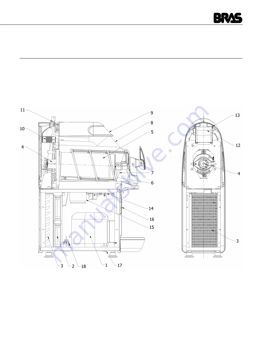
1  APPLIANCE’S DESCRIPTION

This dispenser is designed for the production of iced or frozen drinks such as crushed ice drinks, ice creams and sorbets. The lower

half of the dispenser contains the  cooling system, which consists of a compressor (1), a condenser (3), the related fans (2) and a

solenoid valve to open and close the cooling circuit. The lower half of the dispenser also contains the circuit boards designed to

control operation (14) and (16) and the power supply transformer (15) for both the circuit boards and the geared motor to drive the

mixers.

The upper half of the dispenser contains the transparent tank (8) designed for the food product, which in turn contains the mixer (7)

and the evaporator cylinder (5) which is the unit that chills the product. In addition, the rear of the dispenser houses the electric motor

(4) and the geared motor which drives the mixer, the tank defrosting fan (10) and any LED lamps.

figure 1

The dispenser also features a main ON/OFF switch situated on the left-hand side of the frame underside. In addition, each tank is
fitted with a control panel, situated under the dispenser tap, the functions of which are described below.

BCREAM HD 1/2/3

The model BCream HD, in production starting from year 2014, has the following differences from the previous model:
More powerful mixing system
Cup sensor for ease of dispensing
Graphic display showing a larger number of messages
Improved software for better product handling
Timer for operation programming

Summary of Contents for B-cream HD 1

Page 1: ...d 16 and the power supply transformer 15 for both the circuit boards and the geared motor to drive the mixers The upper half of the dispenser contains the transparent tank 8 designed for the food prod...

Page 2: ...ned off If you press it for two seconds the dispenser switches to Cleaning mode the mixer is on but the cooling is off F Conservation indicator light flashing light product conservation mode selected...

Page 3: ...selected product ready H Ice cream production key allows you to select the ice cream production operating mode On dispensers with more than one tank if you hold this key down while the tank is in ice...

Page 4: ...torage mode PA05 parameter As well as the operating modes described in the Instruction Manual the dispenser may be started up in other modes which can be used for technical support These modes are sum...

Page 5: ...functioning correctly Master switch key H IMPORTANT On dispensers with more than one tank the operating parameters from PA01 to PA10 must be set separately for each tank NAME DESCRIPTION ADJUSTMENT IN...

Page 6: ...in more containers from the factory parameters PA11 to PA 27 are common to all the distributor and therefore can only be adjusted by the control panel on the right container NAME DESCRIPTION ADJUSTME...

Page 7: ...w to verify is the efficiency of the cooling system which can be reduced for example due to a leak of refrigerant gas In order to execute such a check a test with product 90 minutes long is required 7...

Page 8: ...is operating in Service Mode Service Mode or Super AL09 Error Hall probes This alarm stops the operation of the machine AL10 Lack of communication between master and slave card 1 This alarm stops the...

Page 9: ...r filter 2 Loosen the fastening screws and remove the side panels 3 Loosen the screws and remove the front panel Then remove the condensation water drain cover 4 Once you have removed the cover the ta...

Page 10: ...he rear of the board Loosen all the housing securing screws and then remove the board itself 3 To remove the power board you need to disconnect all the connectors then pull down the two side anchor ta...

Page 11: ...EFROSTING FAN AND THE LID PRESENCE SENSORS 1 Remove the air conveyor by pressing on either side Pull the defrosting fan out of its seat in the conveyor The lid presence detectors are situated at the r...

Page 12: ...To update the control board firmware perform the steps described below 1 Collect the programmer to the USB port on the PC where the firmware update files are stored The programmer will be recognised b...

Page 13: ...GRAMMING light will flash for a few seconds and when it remains permanently lit programming has been terminated correctly 4 Switch off the master switch and disconnect the machine from the mains 5 Dis...

Page 14: ...ure 4 Referring to figure 3 proceed as follows 1 Begin the inspection at the High Pressure zone discharge of the compressor Check around the seals 2 Follow the copper pipes to the condenser and check...

Page 15: ...illing unit on the pressure gauge to the charging unit 2 Connect the VAC filling unit to the vacuum pump and open the VAC valve 3 Open the valve on the charging unit and for a moment also open the REF...

Page 16: ...re covered with frost 9 Close the LOW valve disconnect the LOW pipe from the compressor charging pipe and screw the cap onto the bottom of the charging pipe As an indication the temperatures and corre...

Page 17: ...ply circuit board 2 Transformer 9 Display circuit board 3 Electrovalve 10 Temperature probe 4 Compressor 11 Reed safety switches 5 Fan 13 LED board hat optional 6 Geared motor 14 LED Board cop shoulde...

Page 18: ...board 2 Transformer 10 Temperature probe 3 Electrovalve 11 Reed safety switches 4 Compressor 13 LED board hat optional 5 Fan 14 LED Board cop shoulder optional 6 Geared motor 15 LED Strip cop shoulder...

Page 19: ...DIAGRAM POWER SUPPLY DISPLAY MINIGEL 17 TOPOGRAFIC DIAGRAM POWER SUPPLY DISPLAY MINIGEL PLUS KEY M1 Temperature probe M2 MASTER board M3 Faucet Reed switch opt KEY M1 Temperature probe M2 MASTER board...

Page 20: ...ost fan M4 Solenoid valve M12 Earthing M5 Compressor M13 Slave 1 board M6 Display board M14 Slave 2 board M7 Not connected M15 Closed machine without solenoid valve M8 Top cover LED board M16 Open mac...

Page 21: ...49 20 TOP COVER LED TOPOGRAPHY 21 REAR COVER LED TOPOGRAPHY KEY M1 Motherboard M2 LED strip power supply board KEY M1 LED power supply board M2 Rear cover LED strip...

Page 22: ...e density adjustment will be auto matically reduced by one unit Hold down the H key for two seconds to cle ar the alarm message The machine does not start up Message AL04 is indicated on the display T...

Page 23: ...ine to the power supply Message AL13 shown on the display System clock out of order The machine can work but the defrost timer can t be used Replace display pcb Message AL14 shown on the display Batte...

Page 24: ...otor is not functioning short circuit or mechanical blockage Replace the compressor see chapter 10 Electrovalve is not opening coil Replace electrovalve coil Electrovalve is not opening body Replace e...

Reviews: