background image

Operating and Commissioning Instruction for 

Power Factor Control Relay Type CX & CXM

Common Point and Volt free Switching
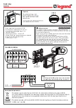
INSTALLATION

Page 2

FUNCTION SWITCH CONTROL POSITIONS

Page 2-4

COMMISSIONING 

Page 4-5

ALARM FUNCTIONS

Page 6

DATA TRANSMISSION

Page 6

FAN CONTROL TEMP. SENSOR OPTION

Page 6

TWO TARGET PF SETTING OPTION

Page 6

COMBI FILTER DETAILS OPTION “K”

Page 7

CXM RELAY READING AND SETTING CT/VT FOR CORRECT MEASUREMENTS

Page 7

WIRING DIAGRAM

Page 8

Fan Control

DIP switch

(see p6)

Function Switch

LED Indication

Calling for Capacitor

steps in

LED Indication

Calling for Capacitor

steps out

LED Indication

Calling for Capacitor

steps in

LED Indication

Calling for Capacitor

steps out

Scroll Buttons

CXM

With Multi - Meter

CX

BPC

Boddingtons P

␸␸

wer Controls

UNIT 1, ZONE D CHELMSFORD ROAD INDUSTRIAL ESTATE, GREAT DUNMOW, ESSEX CM6 1XG, UK  

Tel: +44 (0) 1371 876543  

Fax: +44 (0) 1371 875460

Website: www.boddingtonspowercontrols.co.uk    Email: [email protected]

BODDINGTONS

P o w e r   C o n t r o l s

Summary of Contents for CX

Page 1: ...T FOR CORRECT MEASUREMENTS Page 7 WIRING DIAGRAM Page 8 Fan Control DIP switch see p6 Function Switch LED Indication Calling for Capacitor steps in LED Indication Calling for Capacitor steps out LED Indication Calling for Capacitor steps in LED Indication Calling for Capacitor steps out Scroll Buttons CXM With Multi Meter CX BPC Boddingtons P wer Controls UNIT 1 ZONE D CHELMSFORD ROAD INDUSTRIAL E...

Page 2: ...he removable front plastic nameplate For the CX relay there are two push buttons located either side of the function switch For the CXM multi meter version the keys are on the front of the relay They also allow you to roll through the different measured values of U I P Q S F COSPHI If option L fan control is fitted there will be 2 additional DIP switches S1 S2 located behind the name plate to sele...

Page 3: ...cedure and alarm AL appears in the display The L and F values for each step can be scrolled through with or button and this is a good check to do on regular capacitor bank maintenance The stored values can be re set by pushing buttons and together for longer than 20 sec The regulator will store each step from the moment of re set Automatic mode remains active whilst these checks are made The CXM r...

Page 4: ...equence Relay voltage measurement L2 L3 1 1 1 1 Sequential switching in out with fully automatic recognition of each capacitor size This program could be selected for tuned filter banks where it is essential that each tuned step is switched sequentially Eaut identical to Auto but for single phase operation with relay measurement voltage taken from L1 N E111 identical to 1111 but for single phase o...

Page 5: ...achieve the target power factor 12 With the CX or CXM relay it is not necessary to preset any C k value threshold level when to start to switch a step in out The relay selects the most suitable capacitor size to meet the target power factor Consequently capacitor kvar sizes may be mixed Each time they are switched the reactive output unit of value for each step will be recorded in the CX or CXM re...

Page 6: ...n site the data output from the CX relay can be fed into our Data Logger available as follows DS 21 0 256 MB Approx 2500 events recorded DS 22 _ 0 512 MB Approx 5000 events recorded DS 23 _ 1 024 MB Approx 10000 events recorded The Data Logger can then be taken to the PC for downloading using a WORD programme Optional Features Option L This option has 2 functions 1 Fan Control It is very important...

Page 7: ...1 4000 e g 800A 5A 160 Factory setting 100 Holding the for longer than 2 secs enables rapid roll through E v t ratio using key or in the range of 1 0 350 0 e g 20 kV 0 1kV 200 Factory setting 1 0 Holding the for longer than 2 secs enables rapid roll through Relay type CXM indicates following energy data selectable by using key or C Power Factor U Measuring voltage I Current in selected phase P Tot...

Page 8: ...40 VAC 8 415V 10 Normal Voltage Connection is L2 L3 415V 10 unless otrhewrwise specified on the order L1 N connection ONLY used when relay is specified for single phase supply in which case the connections L2 L3 are not made 415V 10 Normal Voltage Connection is L2 L3 415V 10 unless otrhewrwise specified on the order L1 N connection ONLY used when relay is specified for single phase supply in which...

Reviews: