Bosch D7050, Installation Instructions Manual
The Bosch D7050 boasts an exceptional Installation Instructions Manual designed to simplify your experience with this remarkable product. Delve into its comprehensive manual to ensure seamless setup and operation. Download the user manual for free from manualshive.com and unlock the full potential of your Bosch D7050.
Share
Download


Reviews:
No comments
Related manuals for D7050

CR1018i
Brand: ZEBON Pages: 2
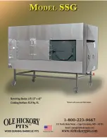
SSG
Brand: Ole Hickory Pits Pages: 44

WT-5442
Brand: La Crosse Technology Pages: 18

iWakeUp Mi4014
Brand: Memorex Pages: 42

System II
Brand: Clifford Pages: 10

MO9922
Brand: MOB Pages: 11

Wake 'n' Shake Voyager
Brand: Geemarc Pages: 2

HR5289/00
Brand: Philips Pages: 2

thefirebeam
Brand: The Fire Beam Pages: 8

28490
Brand: Eleven Twelve Pages: 16

BSM600
Brand: Breville Pages: 24

Shake 'n' Wake
Brand: Safe and Sound Products Pages: 2

Ei168
Brand: RadioLink Pages: 21

B224RB
Brand: System Sensor Pages: 4

BLUE SPLINT
Brand: Spencer Pages: 44

BS-655
Brand: olympia electronics Pages: 2

BSR-6057/A/MAR
Brand: olympia electronics Pages: 3

BS- 657/A
Brand: olympia electronics Pages: 2


