background image

1

CONTENTS:


Reading instructions

Safety instructions!

Description of parts

D


Preparing PRO-CENTER 2000

 •   Mounting large worktable
 •   Altering control unit attachment
 •   Mounting centre squares to 
  

PRO-CENTER 2000

 • 

Increasing drilling accuracy


Adjusting MZK.2880 to ruler

 • 

Setting drilling head at a right angle 


to ruler

 • 

Setting drilling head parallel to ruler

F


Working with MTZ.2880

 • 

System 32 

 • 

Carcase profiles

 • 

Dowels


 - Tops and bases


 - Shelves

G


Maintenance


 2

 3

 5


6

 7
 7
 

8


 10
 

14


 18
 19
 20

20
23


24


PAGE:

EN

!

Summary of Contents for PRO-CENTER 2000

Page 1: ...l unit attachment Mounting centre squares to PRO CENTER 2000 Increasing drilling accuracy E Adjusting MZK 2880 to ruler Setting drilling head at a right angle to ruler Setting drilling head parallel to ruler F Working with MTZ 2880 System 32 Carcase profiles Dowels Tops and bases Shelves G Maintenance 2 3 5 6 7 7 8 10 14 18 19 20 20 23 24 PAGE EN ...

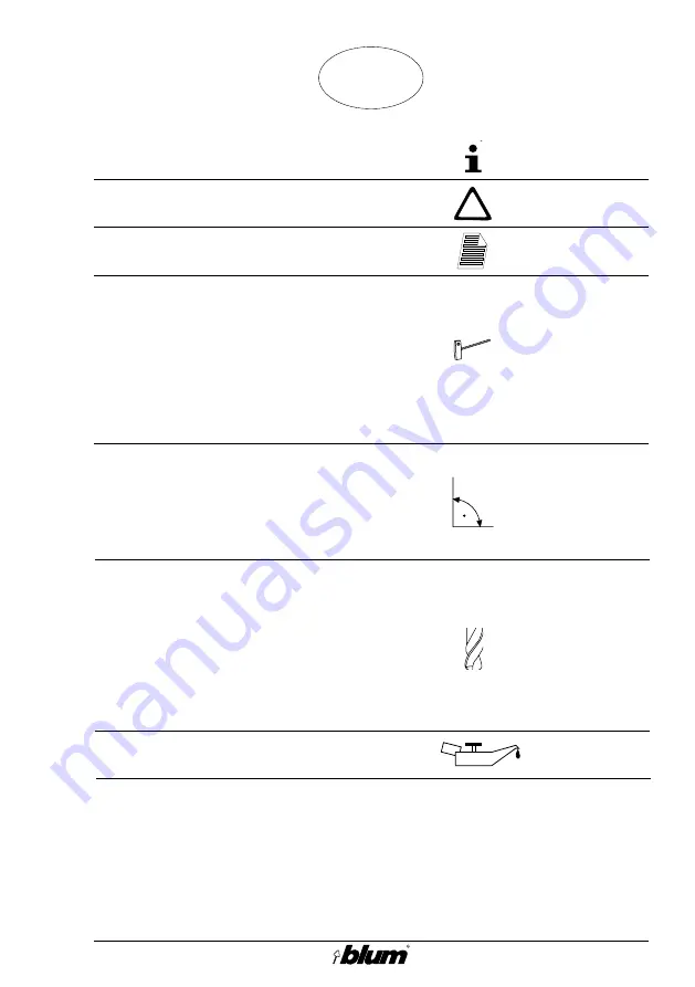
Page 2: ... parts de scribed The individual chapters have been designated with a capital letter and a symbol to facilitate the use of this manual 2 Explanation of symbols and signs This exclamation mark an nounces an important com ment These designations mean that you should refer to the chapter in which these parts are described in detail e g G1 is described in chap ter G The individual chapters have been d...

Page 3: ...ctions of PRO CENTER 2000 first Set operating mode switch E2 to position before changing tools re setting or when working in the drilling area Only use sharp clean drill bits when working Particular care must be taken when working on work pieces which jut out over the worktable Secure the work piece during work Usethemachine shold downclamps to do so If these are insufficient find a suitable faste...

Page 4: ...s necessary on account of room conditions additional noise sources and duration of operation Dust emissions If connected properly to a dust extraction set dust emissions fall clearly below the technical standard value with air velocity reaching a minimum of 20 m s at dust extraction connnectors Depressionamountsto 1060 Pa Do not yourself make any alterations or modifications to the machine Contact...

Page 5: ...le E1 Coupling cover E2 Additional centring devices E3 Hex set screws E4 Adjusting screw E5 Dovetail guide E6 Adjusting pins Ø 10 mm E7 Adjusting blocks 28 37 E8 Cover plate F1 Adjusting blocks 16 19 F2 Straight pins Ø 8 mm G1 Spare coupling Description of parts C Description of parts ...

Page 6: ...upplied with the machine This could have an effect on the drilling depth and drilling distance of the horizontal drilling unit Give the vertical drilling unit a trial run Check drilling depth and adjust the pre positioning screws on the drilling depth revolving handle if necessary Give the horizontal drilling unit a trial run Preparing PRO CENTER 2000 D 352 17 5 Check drilling distance and adjust ...

Page 7: ...the ADDITIONAL CENTRING DEVICE set 2 Changing control unit attachment This only applies to machines with serial numbers up to AC100 Caution Disconnect the machine from the mains and air sup plysystembeforechanging control unit attachment Caution Thecontrolunitattachment of machines with a serial numberofuptoAC100must be retrofitted with the SWI VEL CONTROL UNIT set 352 17 5 ...

Page 8: ...ing head fixing plate with the countersunk screws D3 supplied 4 Increasing drilling accuracy Important Pleasetakenoteofthefollow ing points in order to ensure thegreatestpossibleaccuracy whenworkingwithMZK 2880 Mount PRO CENTER 2000 onto a stable wooden base 352 17 5 D Preparing PRO CENTER 2000 ...

Page 9: ...9 352 17 5 Usethreerulersupports MZV 2000 perextensionrulertoprovidethebest possible support Screw down ruler supports firmly to wooden base D Preparing PRO CENTER 2000 ...

Page 10: ...ont Loosen additional centring devices E2 bylooseninghexsetscrews E3 Push cover plate E8 downwards Loosenorangeadjustingscrews E4 and then tighten slightly Important There should be no play be tween dovetail guide E5 and gear unit Clamp adjusting pins E6 in first and last drill chucks Setting drilling head at a right angle to ruler Adjusting MZK 2880 to ruler E ...

Page 11: ...urn clamping knob and tighten until the control lamp for vertical drilling stops blinking 3 Mounting adjustment aids Settheworktabletoadrillingdistance of approx 40 mm according to the scale Set drilling depth to 16 mm Setthepreselectorto Verticaldrilling and hinge insertion Attach adjusting blocks E7 to ad justing pins E6 Prepare a right angled piece of pressboard measuring approx 600 x 600 x 16 ...

Page 12: ... and move it in until it is positioned against adjusting blocks E7 Check angle of drilling head and correct if necessary Firmly tighten adjusting screws E4 on the left Push additional centring devices E2 outwards until they rest against centre squares and fasten with hex set screws E3 Release start button the vertical drilling unit will return to its initial position Tighten adjusting screws E4 on...

Page 13: ... from machine Remove adjusting blocks E7 and adjusting pins E6 Clamp drill bits in drill chucks Re insert drilling head into machine Give machine trial run Check dimensions of borings Correct angle settings if necessary Adjusting MZK 2880 to ruler E ...

Page 14: ...rds Push coupling cover E1 back Loosen additional centring devices E2 bylooseninghexsetscrews E3 Loosenorangeadjustingscrews E4 and then tighten slightly Important There should be no play be tween dovetail guide E5 and gear unit Clamp adjusting pins E6 in first and last drill chucks Setting drilling head parallel to ruler Adjusting MZK 2880 to ruler E ...

Page 15: ...t back Slide drilling head along the guide until it rests against the stop Move clamping device downwards then turn clamping knob and tighten until the control lamp for vertical drilling stops blinking 3 Mounting adjustment aids Set drilling depth to 16 mm Setthepreselectorto Verticaldrilling and hinge insertion Attach adjusting blocks E7 to ad justing pins E6 Comment If the drilling distance is 3...

Page 16: ...adjusting blocks Clamp down table in this position Check angle of drilling head and correct if necessary Firmly tighten adjusting screws E4 at the front Push additional centring devices E2 outwards until they rest against centre squares and fasten with hex set screws E3 Release start button the vertical drilling unit will return to its initial position Tighten adjusting screws E4 at the back Adjus...

Page 17: ... from machine Remove adjusting blocks E7 and adjusting pins E6 Clamp drill bits in drill chucks Re insert drilling head into machine Give machine trial run Check dimensions of borings Correct parallelism if necessary Adjusting MZK 2880 to ruler E 35 2 1 ...

Page 18: ...ce on worktable and drill for System 32 1 Choose ruler and set stops Recommended rulers Standard ruler MZL 2000 System 32 ruler MZL 2080 a Standard ruler MZL 2000 Set the first stop at 256 mm X Position all other stops at an interval of 544 mm b System 32 ruler MZL 2080 Set the first stop at 128 mm Set X by means of zero point adjust ment See PRO CENTER 2000 page 58 Set all other stops at an inter...

Page 19: ...ver to drill right and left components That means higher accuracy as stops need only be set once Sets stops at intervals desired 2 Insert drilling head and ruler Insert ruler into machine Clamp drill bits in drill chucks 2 x 5 mm Ø clockwise 2 x 5 mm Ø anti clockwise Insert drilling head at a right angle to ruler 3 Adjust drilling depth 4 Set worktable to drilling distance desired 5 Proceed to dri...

Page 20: ...to first bore hole 2 Insert drilling head and ruler Insert ruler into machine Clamp drill bits in drill chucks 5 x 8 mm Ø clockwise 4 x 8 mm Ø anti clockwise or 5 x 10 mm Ø clockwise 4 x 10 mm Ø anti clockwise Insert drilling head parallel to ruler 3 Adjust drilling depth 4 Set worktable to drilling distance desired 5 Adjust the drilling depth and drill ing distance of horizontal drilling unit 6 P...

Page 21: ... pin F2 for holes with an 8 mm Ø and adjusting block F1 Correct drilling distance Z if neces sary b Setting worktable to drilling dis tance Clamp adjusting pins E6 in first and last drill chucks Insert drilling head parallel to ruler Attach adjusting blocks F1 to ad justing pins E6 Comment If the drilling distance is to be 8 or 9 5 mm mount the adjustment blocks with the correspondingdimensions 16...

Page 22: ...against adjusting blocks Clamp down table in this position Check angle of drilling head and correct if necessary See chapter E Settingdrillingheadparalleltoruler Release start button Comment This worktable setting can be easily recovered by pre set ting revolving handle for worktable adjustment see PRO CENTER 2000 chapter E Pre setting re volving handle for worktable adjustment Working with MTZ 28...

Page 23: ...hine Clamp drill bits in drill chucks 5 x 8 mm Ø clockwise 4 x 8 mm Ø anti clockwise or 5 x 10 mm Ø clockwise 4 x 10 mm Ø anti clockwise Insert drilling head at a right angle to ruler 3 Adjust drilling depth 4 Set worktable to drilling distance desired Comment We recommend setting the first bore hole at 32 mm 5 Proceed to drill Place work piece on worktable and drill for dowels Working with MTZ 28...

Page 24: ...unctioning properly Replaceanydamagedparts withgenuinespareonesimmediately Replace blunt drill bits with sharp ones Caution Replacebrokenordamaged parts immediately Use only genuine spare parts made by Blum 2 Replacing damaged coupling Remove damaged coupling with a blunt screwdriver Push spare coupling G1 onto shaft until it is flush with top of shaft Maintenance G ...

Page 25: ...25 ...

Page 26: ...26 Notes ...

Page 27: ...27 Notes ...

Page 28: ...28 Id Nr 173 399 0 Printed in Austria BA 17 02 EN 01 2002 BAU0003173112 IDX05 ...

Reviews: