BW-2500
PREMIER
PLUS
I N S T A L L A T I O N M A N U A L
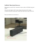
Please read this Manual carefully before attempting to install this system.
BEFORE INSTALLING THE BW-2500 PREMIER PLUS
• DO read through this installation manual.
• DO NOT install the alarm brain in an engine compartment.
• The alarm may arm itself when power is first connected.This is a normal condition.
ITEMS SUPPLIED WITH THE BW-2500
BWS-2502
Receiver and Control Module
BWS-260
Valet Switch
BWS-385
2-Button, 3-channel, Code
BWS-180
LED Status Indicator
Learning Transmitters (2)
BWS-12025
Wiring Harness, Fuseholder,
MTS-20W
Programmable, Multi-tone,
and Fuse
120 dB Siren
SPDT
Relay
BWS-296
Dual Zone Electronic
BRS-003
Relay Socket
Shock Sensor
OPTIONAL ACCESSORIES
Backup Battery ..................................................
BWS-500
Radar Field Sensor.........................................
MAS-2
Remote Starting.................................................
RAS-101
Window Rollup.............................................
WRM-2
Leather Transmitter Case ...............................
BWS-390
Power Door Lock........................................
PDL-50
Trunk Release ........................................................
TR-100
SPECIFICATIONS
Operating voltage ...............+12 VDC Neg. Ground
Code Learning ......................................3 Codes Max.
Current consumption .........5 mA (max) disarmed.
Siren output drive ......................................3 Amperes
Automatic reset........................................60 seconds.
Door Lock/Unlock Output ...................(-) 500 mA.
Channel 2 Output Drive ........................(-) 500 mA.
Channel 3 Output Drive..................(-) 500 mA, variable.
Remote control transmit freq.............................310 mHz.
Passive arming delay ............................30 Seconds approx.
Auxiliary output drive..........................250 mA maximum.
Flashing output drive ............................10 Amp maximum.
Trigger inputs..............................................1) Neg. pnswtch.
1) Pos. pnswtch. 1) Neg. sensor or aux. pnswtch.
Dome light output.....................................500 mA ground.