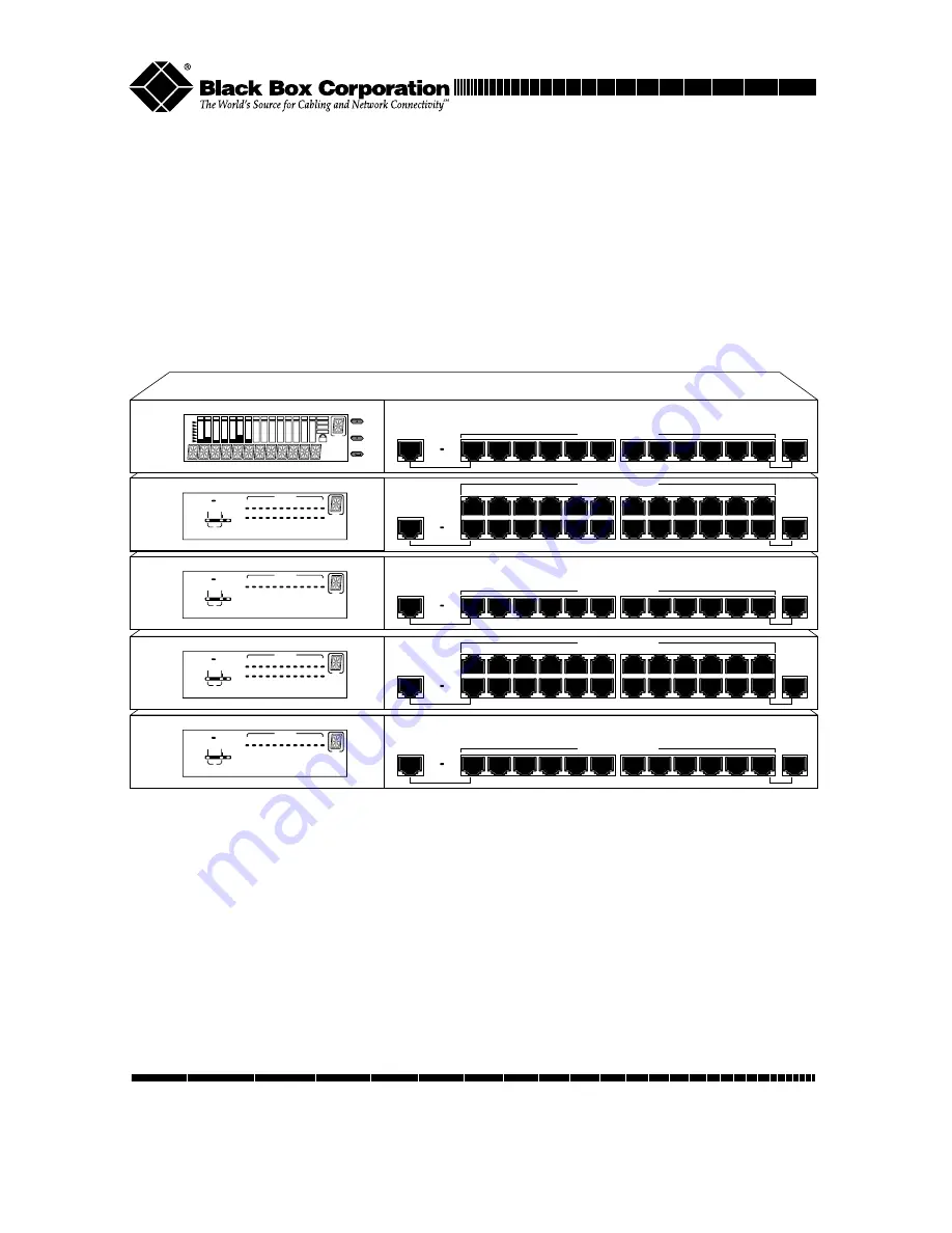
background image

MDI-II

10/100 Managed Hub

MDI-II

1x

2x

3x

4x

5x

6x

9x

8x

7x

10x

11x

12x

Switch Module

Installed

Power

100M

Collision

Forward

Int.

Switch

Ext.

Switch

Link/RX

1 2 3 4 5 6 7 8 8 10 11 12

ID

10M

MDI-II

MDI-II

1x

2x

3x

4x

5x

6x

9x

8x

7x

10x

11x

12x

13x

14x

15x

16x

17x

18x

21x

20x

19x

22x

23x

24x

10/100 Managed Hub

Switch Module

Installed

Power

100M

Collision

Forward

Int.

Switch

Ext.

Switch

Link/RX

1 2 3 4 5 6 7 8 9 10 11 12

13 14 15 16 17 18 19 20 21 22 23 24

ID

10M

MDI-II

10/100 Managed Hub

MDI-II

1x

2x

3x

4x

5x

6x

9x

8x

7x

10x

11x

12x

Switch Module

Installed

Power

100M

Collision

Forward

Int.

Switch

Ext.

Switch

Link/RX

1 2 3 4 5 6 7 8 8 10 11 12

ID

10M

MDI-II

MDI-II

1x

2x

3x

4x

5x

6x

9x

8x

7x

10x

11x

12x

13x

14x

15x

16x

17x

18x

21x

20x

19x

22x

23x

24x

10/100 Managed Hub

Switch Module

Installed

Power

100M

Collision

Forward

Int.

Switch

Ext.

Switch

Link/RX

1 2 3 4 5 6 7 8 9 10 11 12

13 14 15 16 17 18 19 20 21 22 23 24

ID

10M

MDI-II

10/100 Managed Hub

MDI-II

1x

2x

3x

4x

5x

6x

9x

8x

7x

10x

11x

12x

Switch Module

Installed

Prev

Next

Enter

ID

Installation & User Guide

10/100 M

ANAGED 

H

UB

JUNE 1999

LH8112A
LH8124A

LH8112A-S
LH8124A-S

Order toll-free in the U.S. 24 hours, 7 A.M. Monday to midnight Friday: 877-877-BBOX
FREE technical support, 24 hours a day, 7 days a week: Call 724-746-5500 or fax 724-746-0746
Mail order:  Black Box Corporation, 1000 Park Drive, Lawrence, PA 15055-1018
Web site: www.blackbox.com   •   E-mail: [email protected]

CUSTOMER

SUPPORT

INFORMATION

Summary of Contents for LH8112A

Page 1: ...5 6 7 8 8 10 11 12 ID 10M MDI II MDI II 1x 2x 3x 4x 5x 6x 9x 8x 7x 10x 11x 12x 13x 14x 15x 16x 17x 18x 21x 20x 19x 22x 23x 24x 10 100 Managed Hub Switch Module Installed Power 100M Collision Forward I...

Page 2: ...ll rights reserved No part of this publication may be reproduced stored in a retrieval system translated transcribed or transmitted in any form or by any means manual electric electronic electromagnet...

Page 3: ...rview 16 Installation 17 Choosing a Location 17 Stacking 17 Rack Mounting 17 Using Cascade Cables 17 Constructing a Management Stack 18 Position Within the Stack 18 Master Hub Role 18 Client Hub Role...

Page 4: ...FX 34 Managing Through the Mini Console 37 Mini Console Overview 37 Features 37 VFD Display 38 Observing Basic Port Information 38 Port Indicator Definition 39 Console Keys 39 Menu Tree 40 Observing N...

Page 5: ...ormation Menu 60 Master Hub Configuration Console Management 61 Connecting the Console Interface 61 Menu Convention 62 Using the Console Program 64 Logging In 64 Main Menu 65 Monitoring System Informa...

Page 6: ...105 Address Search Information 107 Broadcast Storm Protection 109 Broadcast Storm Detected 111 User Authentication 112 System Utility 114 System Download 115 System Restart 116 Factory Reset 118 Login...

Page 7: ...b series consists of masters and managed clients with 12 or 24 ports The features and functions of the 10 100 Managed Hub series makes it a powerful cost effective solution for large campus networks a...

Page 8: ...ncludes an LED panel 24 dual speed auto sensing ports 2 MDI II ports and a switch module expansion slot The LH8124A S can be fully managed by any master hub model MDI II MDI II 1x 2x 3x 4x 5x 6x 9x 8x...

Page 9: ...g expansion modules see below The lower slot accepts switch expansion modules See Chapter 2 Using Expansion Modules for more information The upper slot is for the Network Management Unit NMU only Expa...

Page 10: ...ng The monitor can notify the manage ment station of failure and can store historical statistical information about the failure The management station can play this historical information back in an a...

Page 11: ...ort it was seen This capability can be used to collect the necessary information for mapping the topology of a network Up to 8 MAC addresses can be searched simultaneously You can configure address se...

Page 12: ...ed in the hub Front Panel LH8112A S 12 Ports Front Panel LH8124A S 24 Ports MDI II MDI II 1x 2x 3x 4x 5x 6x 9x 8x 7x 10x 11x 12x 13x 14x 15x 16x 17x 18x 21x 20x 19x 22x 23x 24x 10 100 Managed Hub Swit...

Page 13: ...rs 24 Port Power The Power LED is on when the power cable is plugged into the hub and a wall socket Link Rx The Link Rx LED is on for each connected port and blinks for ports receiving transmissions C...

Page 14: ...10Mbps segment through the internal switch 10M On Off On A 100Mbps transmission being received by 10Mbps segment through the external switch 100M On On On A 10Mbps transmission being received by 100Mb...

Page 15: ...itch module installed LED 12 10 100 ports and 2 MDI II ports The front panel for model LH8124A supports the Mini Console switch module installed LED 24 10 100 ports and 2 MDI II ports The Switch Modul...

Page 16: ...le Mini Console Rear Panel Overview The rear panel of each hub in the 10 100 Managed Hub series supports two expansion slots two cascade ports and an AC power socket The cascade ports are used for cas...

Page 17: ...n make up a stack The master can be positioned anywhere in the stack so you can add to a stack without re positioning the hubs Rack Mounting Rack mounting brackets are included to mount hubs in a stan...

Page 18: ...master hub can be positioned anywhere in a stack and automatically assigns the ID of each hub according to its position in the stack Master Hub Role The master is used to manage and configure other hu...

Page 19: ...naged Hubs can isolate one or both segments 10 Mbps and 100 Mbps segments from the other hubs in a stack When a segment is isolated it does not repeat to the other segments in the hub or to other segm...

Page 20: ...ard in the workstation to a hub port Connecting Ethernet Hubs or Devices Connect 10Mbps devices using UTP STP Cat 3 4 or 5 cables with RJ 45 connectors enabling sending receiving to or from other 10Mb...

Page 21: ...ng fiber cable Connecting Fast Ethernet Hubs Connecting Other Dual Speed Hubs Other dual speed hubs can be connected to the ports of the 10 100 Managed Hubs Each port can auto sense the connected port...

Page 22: ...22 10 100 Managed Hub...

Page 23: ...default The Admin State of a bridge module must be config ured using Console or Web Based Management after installation Internal Bridge Function The Internal Bridge Function is used for bridging 10Mbp...

Page 24: ...d before the bridging functions take effect Please read this section carefully before installing modules IMPORTANT These modules are not hot swappable You must remove power from the hub before install...

Page 25: ...ugh the guides as shown below AC LINE 100 240VAC 50 60Hz 1 5A MAX Stackable Up NMU Switch Transceiver Down Insert the Module 5 Turn the two knobs on the new bridge module until they are securely attac...

Page 26: ...tion on Bridge Module configuration refer to Chapter 4 Console Management Controlling Devices TX Module LED Indicators The LEDs on each module indicate port activity All LEDs are green Link On indicat...

Page 27: ...On indicates a transmission in progress RX On indicates receiving data FDX On indicates the port is set to full duplex Off indicates the port is set to half duplex Collision On indicates collision occ...

Page 28: ...e default settings are as follows Bridge Function setting Internal Default Backpressure setting Disabled Default Module LH8100C 2TX Bridge Jumpers The default jumper setting of the LH8100C 2TX module...

Page 29: ...pansion Modules 29 Jumpers Module LH8100C 2TX 1 JP18 2 3 1 JP16 2 3 JP15 JP14 JP13 JP12 JP11 JP10 JP9 JP8 JP7 JP6 JP5 JP4 JP3 JP2 JP1 JP18 Backpressure 2 3 EXT SW 1 2 INT SW JP1 I JP16 Disable Enable...

Page 30: ...he default settings are as follows Bridge Function setting Internal and External enabled Default Backpressure setting Disabled Default Module LH8100C 3TX Bridge Jumpers The default jumper setting of t...

Page 31: ...Using Expansion Modules 31 Jumpers Module LH8100C 3TX 3 2 1 3 2 1 JP7 JP6 JP5 JP4 JP2 JP1 2 3 JP4 JP6 Int Sw Enable 1 2 Int Sw Disable JP2 2 3 JP7 Backpressure 1 2 Backpressure dis JP1...

Page 32: ...Default Module LH8100C 2FX Bridge Jumpers The default jumper setting of the Module LH8100C 2FX is internal bridge disabled To enable the internal bridge and disable the external bridge change the jump...

Page 33: ...33 Jumpers Module LH8100C 2FX 3 JP19 2 1 3 JP1 2 1 3 JP17 2 1 JP16 JP15 JP14 JP13 JP12 JP11 JP10 JP9 JP8 JP7 JP6 JP5 JP4 JP3 JP2 JP1 JP19 Backpressure 2 3 EXT SW 1 2 INT SW JP2 I JP17 Disable Enable...

Page 34: ...internal bridge disabled The external distance extender is always enabled To enable the internal bridge change the jumpers JP3 JP5 JP7 from 1 2 to 2 3 Jumper JP1 Duplex Jumper JP1 1 2 half duplex 2 3...

Page 35: ...Expansion Modules 35 Jumpers Module LH8100C 3FX 3 JP1 2 1 1 2 3 3 2 1 JP8 JP7 JP6 JP5 JP3 JP2 JP1 Backpressure Backpressure dis 2 3 Int Sw Enable 1 2 Int Sw Disable JP3 JP5 7 JP2 JP8 2 3 1 2 HDX FDX 1...

Page 36: ...36 10 100 Managed Hub...

Page 37: ...Mini Console The Mini Console is only available for the 10 100 Managed Hub master units Features High definition display panel text and graphics Message Zone Gauge Bars Indicators Port Indicators Port...

Page 38: ...ation port status and serves as an indicator for groups or ports Lock Icon Indicates that the control panel configuration is locked G A Port group indicator displays status of ports 1 to 12 G B Ports...

Page 39: ...the administrator has disabled the port Normal ON The Link is down and the administrator has disabled the port Flashing OFF Link is up and receiving data Normal BLINKING The port is partitioned by the...

Page 40: ...em indicating it is the current default Menu Tree The menu tree consists of these seven main level menus Utilization Group Select Statistics Port Status Port Configuration Unit Configuration System In...

Page 41: ...CKED PSW ALL PORT ENABLED PORT 1 PORT N DISABLED AUTO NEGO 10BASE T 100BASE X UNIT CONFIG CONSOLE LOCK LOCK NETWORK CONFIG IP ADDRESS SUBNET MASK DEF GATEWAY SET PASSWORD SYS RESTART CONTINUE CANCEL S...

Page 42: ...ization in the 10Mbps segment and the total utilization in the 100Mbps segment at the time the statistics were taken by the hub The total utilization history represented by the seven columns in each s...

Page 43: ...until GROUP SELECT displays in the Message Zone 2 Press Enter Several bars under the Port number indicate the current group as shown below Group Select 3 Press Next until the group number you wish to...

Page 44: ...octets but excluding framing bits and were otherwise well formed SHORT EVENTS The total number of packets received that were less than 64 octets including FCS octets but excluding framing bits and we...

Page 45: ...ge Zone Statistics 2 Press Enter to go to the port selection menu and select a port for viewing In the port selection menu six units of the gauge bars below the port number indicate the current port T...

Page 46: ...own below ID Master WWW SNMP O O B 10 20 40 1 3 5 80 K 1 2 3 4 5 6 7 8 9 10 11 12 13 14 15 G A G B G C G D Readable Form 5 Press Next to scroll through each type of counter 6 Press Enter to view the v...

Page 47: ...he group cursor under the port ID indicator as shown below Port Status 2 Press Enter ALL PORTS displays in the Message Zone When monitoring all ports the gauge bar columns are divided into 24 one for...

Page 48: ...O B 10 20 40 1 3 5 80 K 1 2 3 4 5 6 7 8 9 10 11 12 13 14 15 G A G B G C G D 100Mbps Ports 5 Press Next to view other port status information The status information that is available is listed in the...

Page 49: ...ssage Zone 2 Press Enter to go to the port selection menu ALL PORTS displays in the Message Zone 3 Press Next to select an individual port PORT 1 displays in the Message Zone After a slight delay the...

Page 50: ...ow Port Configuration Configuring ALL PORTS 1 With PORT CONFIG displayed in the Message Zone press Enter to go to the port selection menu All PORTS displays in the Message Zone 2 Press Enter The first...

Page 51: ...enu 2 Press Next to select an individual port 3 Press Enter The configuration of the selected port displays in the Message Zone Six gauge bars below the port number indicate the current port Three gau...

Page 52: ...ting press and hold down Enter until an appears before the desired setting the is removed from the previous setting Port Setting Default Optional Settings AUTO NEGO 10BASE T 100BASE X ENABLE Disable U...

Page 53: ...Unit Configuration Options Console Lock Lock Network Config IP Address Subnet Mask and Default Gateway Set Password Set new password System Restart Restart hub System Default Reset hub to factory con...

Page 54: ...5 80 K 1 2 3 4 5 6 7 8 9 10 11 12 13 14 15 G A G B G C G D Locked State Unlocking the Mini Console Once unlocked a password is not required to make configuration settings with the Mini Console The con...

Page 55: ...connections to the hub Network Configuration Configuration Default IP ADDRESS 000 000 000 000 SUBNET MASK 000 000 000 000 DEFAULT GATEWAY 000 000 000 000 IP Address Configuration 1 Select UNIT CONFIG...

Page 56: ...will shift to the left to make room for the last digits When setting the IP address is complete the system will validate the IP address If the IP address is valid the display will show the IP address...

Page 57: ...2 CONFIG and press Enter 3 Scroll to BAUD RATE and press Enter 4 Press Next until the baud rate that you want to set displays in the message zone 5 Press Enter to set the new baud rate An appears befo...

Page 58: ...4 Scroll to SET PASSWORD and press Enter 5 Enter a new password and press Enter to exit the password configuration SET PASSWORD displays in the message zone 6 Press Next until MAIN MENU displays in th...

Page 59: ...ations are selected from the SYS DEFAULT menu a sub menu of the Main Menu item UNIT CONFIG The factory defaults are the settings that were set at the factory before shipping the hub Restore the defaul...

Page 60: ...software version and the network configuration settings IP Address Subnet Mask and Default Gateway System Information The following system information is cycled through in the Mini Console System Info...

Page 61: ...following 1 Install a terminal emulation application such as Windows Hyperterminal on your PC 2 Configure the terminal emulation application as follows Baud rate 9600 Parity None Data bits 8 Stop bit...

Page 62: ...s of fields and commands of console management menus and their usage Menu Conventions System Download Menu x Bootp Request Illegal File Name Unknown xyz Save Exit To Main Menu Help File Download Reque...

Page 63: ...d the procedure associated with this field will be performed Toggle Input Item Use the space bar to toggle between options that are enclosed in angle brackets Text Input Item Text fields appear betwee...

Page 64: ...times to bring up the login menu The login menu appears similar to the illustration below Logging In When logging in for the first time enter the User Name ADMIN and the password the default is blkbo...

Page 65: ...st item highlighted as below Main Menu The Main Menu has six major selectable items System Information Management Setup Device Control Network Management User Authentication and System Utility System...

Page 66: ...n about the system You can view the system software and hardware information and config ure the system configurations as shown below System Information You can specify up to 48 alphanumeric characters...

Page 67: ...easy and unambiguous means for determining what kind of device is being managed System Up Time The time since the network management portion of the system was last restarted or powered on System Cont...

Page 68: ...llows you to configure the IP Address Subnet Mask Default Gateway and SLIP Address Serial Port Configuration Allows you to configure the serial port connections SNMP Community Setup Configure communit...

Page 69: ...etwork Configuration Menu allows setting up Ethernet and SLIP connections to the hub Network Interface 1 is used to configure Ethernet connections and Network Interface 2 is used to configure SLIP con...

Page 70: ...before the IP address subnet mask and default gateway can take effect To ensure that the new information is correct a ping should be done from another device connected to the 10 100 Managed Hub NOTE T...

Page 71: ...le Baud Rate The current serial port baud rate that can be configured from the Serial Port Configuration Menu Character Size 8 bits character size Parity None Stop Bits 1 stop bit IP Address The dotte...

Page 72: ...onsole Mode settings select Console Mode in the Serial Port Configurations Console Mode settings are read only Use the settings as shown below Console Operation Mode Out of Band Mode Out of Band mode...

Page 73: ...kes effect if Out of Band management is enabled When SLIP is enabled the EIA 232 port can be used for SLIP only The EIA 232 port cannot be used to gain access to a management session via VT100 termina...

Page 74: ...Community names are case sensitive Private and private are considered different You cannot enter the same name more than once an error message appears at the bottom of the panel Press the Esc key to c...

Page 75: ...enu 2 2 Enter a name in the Input field 3 Set the access right and status 4 Highlight ADD and press Enter the new name is entered and displayed To edit a community name 1 Enter an existing name in the...

Page 76: ...You can set up six trap receivers You can configure the following Community Name The authorized SNMP community string of the remote network manager maximum 16 characters IP Address The IP Address of t...

Page 77: ...he configuration menu for the selected index as shown below Configuring a Community Name The Community Name can be edited the IP Address can be configured and the Status can be set to Active or Inacti...

Page 78: ...ce bar to toggle between settings Select Save and press Enter to save the setting Management Capability Setup Menu This menu lets you enable or disable Web Based Management and Out of Band Management...

Page 79: ...agement Control You can enable or disable Out of Band management When connecting with local console this setting takes effect immediately When connecting with Telnet the system must be restarted befor...

Page 80: ...he Trap Filter Menu as shown below Trap Filter Menu This menu lets you enable or disable trap filters for those traps defined by RFC1215 and RFC1516 Marking a trap filter disables the trap and no trap...

Page 81: ...the hubs in a stack Repeater Port Control Status Allows you to read and configure ports on any hub in a stack 2 3 Port Bridge Module Control Status Allows you to set up any Bridge Switch Modules such...

Page 82: ...l Status Group Number The ID number of a hub in the stack the range is 1 6 Group Status Port Capacity The maximum number of ports that can be contained within the group 12 24 Repeater Type The repeate...

Page 83: ...e configurable functions and provides option fields Use Ctrl S to toggle between options Group Admin State Allows you to isolate one or both segments from the other hubs in a 10 100 Managed Hub When a...

Page 84: ...t the link status of each port to Link Down That will cause a Link Status Change event to be raised Reset Counters Only The counters of each port will be reset to 0 but the function logic will be held...

Page 85: ...eater Port Control Status The Repeater Port Control Status menu provides information about the hub s port status A hub can be selected with the PREV GROUP and NEXT GROUP commands and its ports selecte...

Page 86: ...titioned Auto Partitioned The port is partitioned Speed This is the current speed of this port The default is Auto Negotiate Auto Negotiate The port speed is automatically negotiated to the fastest sp...

Page 87: ...to half duplex Force 10 TP The port speed is forced to 10Mbps Force 100 TP The port speed is forced to 100Mbps Link Status Change Notify Enable The trap is sent Disable The trap is not sent NOTE When...

Page 88: ...t for a given module TP port with RJ 45 interface Multi mode with SC type interface External Port Link Status The current link status of the installed module Read only Link Up Link Down External Port...

Page 89: ...or the internal bridge to function NOTE The internal bridge must be enabled in hardware with the Jumper switch settings before the Admin state can be enabled Refer to Chatper 2 Using Expansion Modules...

Page 90: ...t the primary link fails the secondary link becomes active The secondary link stays active even if the primary link recovers You must manually reset the primary link status to active in order to re in...

Page 91: ...or more than five seconds then the active link failure is detected and port switch over is performed and a trap is sent to the trap receivers Enable A trap is sent to the trap receivers if a switch ov...

Page 92: ...s of the redundant link is enable If the status is suspend then the link pair is reactivated but no trap is sent Configuring Link Pairs 1 Select a Link Pair 1 24 Use NEXT PAGE to select pairs 13 throu...

Page 93: ...ing the Link Pair number of an existing Link Pair and reconfiguring the rest of the columns then select Save the Link Pair is updated to the new settings Deleting a Link Pair You can delete a Link Pai...

Page 94: ...u to set up secure ports that allow access by a single authorized MAC address Group Number The hub ID number that is assigned to the 10 100 Managed Hub 1 6 Port Number The port number of the hub that...

Page 95: ...ice that is allowed to connect with this particular port Intrusion Action This is the action that is performed when the hub detects an intrusion of an unauthorized MAC address No Action No action will...

Page 96: ...both 10Mbps segment and 100Mbps segment Repeater Group Statistics Information Displays the statistic counters for each hub Repeater Port Statistics Information Displays the statistic counters for a s...

Page 97: ...o detect if broadcast storming exists in the network Broadcast Storm Detected Each hub port or optional module port which causes the broadcast storm displays Repeater Statistics Information Selecting...

Page 98: ...s The number of transmission collisions that have occurred in this hub Total Frames The number of frames received in this hub Total Errors Total errors received by the port including FCS errors Align...

Page 99: ...roup Number Counters are displayed in Absolute or Relative values by toggling the display mode Absolute values represent the value collected since system start You cannot clear absolute counters using...

Page 100: ...d not including FCS Error and Collision Event Total Octets The total number of octets contained in the valid frames that have been received on the ports of this hub Tx Collisions The total number of t...

Page 101: ...in Absolute and Relative values Absolute Repeater Port Statistics Information Menu Absolute The Repeater Port Statistics Information Menu displays counter informa tion for the current port of the cur...

Page 102: ...t Number Port number of selected group 1 to 12 24 Display Mode Display counters in Absolute or Relative values Readable Frames Total readable frames received by the port Broadcast Packets The total nu...

Page 103: ...ere less than 64 octets due to collisions or activity duration that was greater than the ShortEventMaxTime event and less than the ValidPacketMinTime event Collisions Total collisions Late Events Tota...

Page 104: ...ically recovers Symbol Errors 100Mbps only Total symbol errors for 100Mbps transmissions This counter is incremented by one for each valid length packet received at the port with at least one occurren...

Page 105: ...Menu Source Address Changes This counter is incremented by one for each time that the Last Source Address for this port changes This may indicate whether a link is connected to a single device or ano...

Page 106: ...in the tracking list contains the value that is given by the Last Source Address for this port This list can contain 15 entries The list does not age out the first entries are deleted to accommodate n...

Page 107: ...and report on which port it was seen This capability can also be used to collect the necessary information for mapping the topology of a network Up to 8 MAC addresses can be searched simultaneously Ad...

Page 108: ...hip of the entry and the value of Address Search Lock is incremented to 1 Failure of the set operation indicates that some other manager has obtained ownership of the entry Address Searched Specify MA...

Page 109: ...ndition still exists The partitioned hub port is auto recovered to normal operation once the broadcast storm condition is released Broadcast Storm Protection Menu You can configure the broadcast thres...

Page 110: ...isabled Once a port is partitioned due to broadcast storm the Broadcast Storm protection function will continue to monitor the port based on the following rule a The port is disabled for 15 seconds en...

Page 111: ...This menu displays a list of ports with a detected Broadcast Storm Broadcast Storm Detected Menu Each broadcast storm is detected and the hub and port number are listed in this menu If there have been...

Page 112: ...tion Menu To define each user authentication select an index number and press Enter Use the ADD command to add a name A user name and password can be deleted using the DELETE command Select the EXIT c...

Page 113: ...113 User Authentication Menu editable User Authentication Menu updated Select the index number first and press Enter Enter a user name of up to 12 characters and a password of up to 6 characters speci...

Page 114: ...hat has become corrupted System Restart The system can be restarted at any time and is required after certain configuration settings are made Factory Reset The system can be reset to the original sett...

Page 115: ...quest select the appropriate download function enter the filename with the full path save the configuration and finally restart the device from the System Restart Menu System Download Menu This menu l...

Page 116: ...ion Boot ROM Code download 110Vxxx BT Web Pages Database Information Download 110Vxxx WEB System Software Download 110Vxxx RT where xxx is the version number To download TFTP code perform the followin...

Page 117: ...ssage informs the user that system restart is going to be performed right now Warm A warm restart restarts the hub at the runtime code For most cases a warm restart is sufficient except in the case of...

Page 118: ...Reset Menu lets you return all Hub settings to the original default settings When you issue a factory reset all of your custom settings are overwritten To perform the factory reset do the following s...

Page 119: ...o factory defaults 3 Select Execute and press Enter When Execute and Enter are selected a warning message informs the user that system configuration data will be reset Login Timeout Interval Login Tim...

Page 120: ...tem settings Configuration Upload Setting Menu Enter the TFTP Server IP Address and the chosen file name for example filename CFG and the path where the files will be uploaded on the server Select Sav...

Page 121: ...iew the status of a download Select Submit to make the Upload Request TFTP Server IP Address The IP address of the server where the configuration files will be uploaded Configuration File Name The nam...

Page 122: ...ecified Configuration Filename field is full Timeout The TFTP upload timeouts expired at 20 seconds A progress bar displays in the menu showing the progress Other Other errors that are defined by the...

Page 123: ...stics at a glance Client Rich diagnostic LEDs indicate Link Rx per port Forwarding indicator for both 10 100Mbps segments Collision indicator for both 10 100Mbps segments 10 100Mbps indicators with in...

Page 124: ...n control per port security 24 pairs of redundant link Broadcast storm protection BOOTP TFTP software download supported Console Telnet Management VT 100 terminal interface supported Local console man...

Page 125: ...H8124A 12 24 ports auto sensing 10 100Mbps Master Hub with Local console Remote Telnet management SNMP Web Based Management Mini Console Management LH8112A S LH8124A S 12 24 ports auto sensing 10 100M...

Page 126: ...nment This equipment generates uses and can radiate radio frequency energy and if not installed and used in accordance with the instruction manual may cause harmful interference to radio communication...

Page 127: ...mente con carritos o pedestales que sean recomendados por el fabricante 7 El aparato el ctrico debe ser montado a la pared o al techo s lo como sea recomendado por el fabricante 8 Servicio El usuario...

Page 128: ...o nicamente de acuerdo a las recomendaciones del fabricante 15 En caso de existir una antena externa deber ser localizada lejos de las lineas de energia 16 El cable de corriente deber ser desconectado...

Page 129: ...9200 38400 ALL PORTS PORT 1 PORT N READABLE FRM READABLE OCT FCS ERRORS ALIGN ERRORS FRM TOO LONG SHORT EVENTS RUNTS COLLISIONS LATE EVENTS VERY LONG EN RATE MISMATCH AUTO PART TOTAL ERRORS PORT 1 POR...

Page 130: ...unction is enabled with the on board jumpers 10Mbps and 100Mbps segments cannot communicate The internal switch must be enabled using local console management through connections from the RS 232 port...

Page 131: ...tscape menu bar select Edit select Preferences from the drop down list click the sign beside Advanced and then select Clear Memory Cache Q I do not see the graphic of the unit when I use Internet Expl...

Page 132: ...5660 810001 002 A 6 99 Copyright 1999 Black Box Corporation All rights reserved 1000 Park Drive Lawrence PA 15055 1018 724 746 5500 Fax 724 746 0746...

Reviews: