background image

Order toll-free in the U.S. or for FREE technical support 24/7: Call 877-877-BBOX 
(outside U.S. call 724-746-5500)
www.blackbox.com  •  [email protected]


Contact 

Information

User Manual

Switch four or eight HDMI 2.0 and HDCP 2.2 compliant signals.

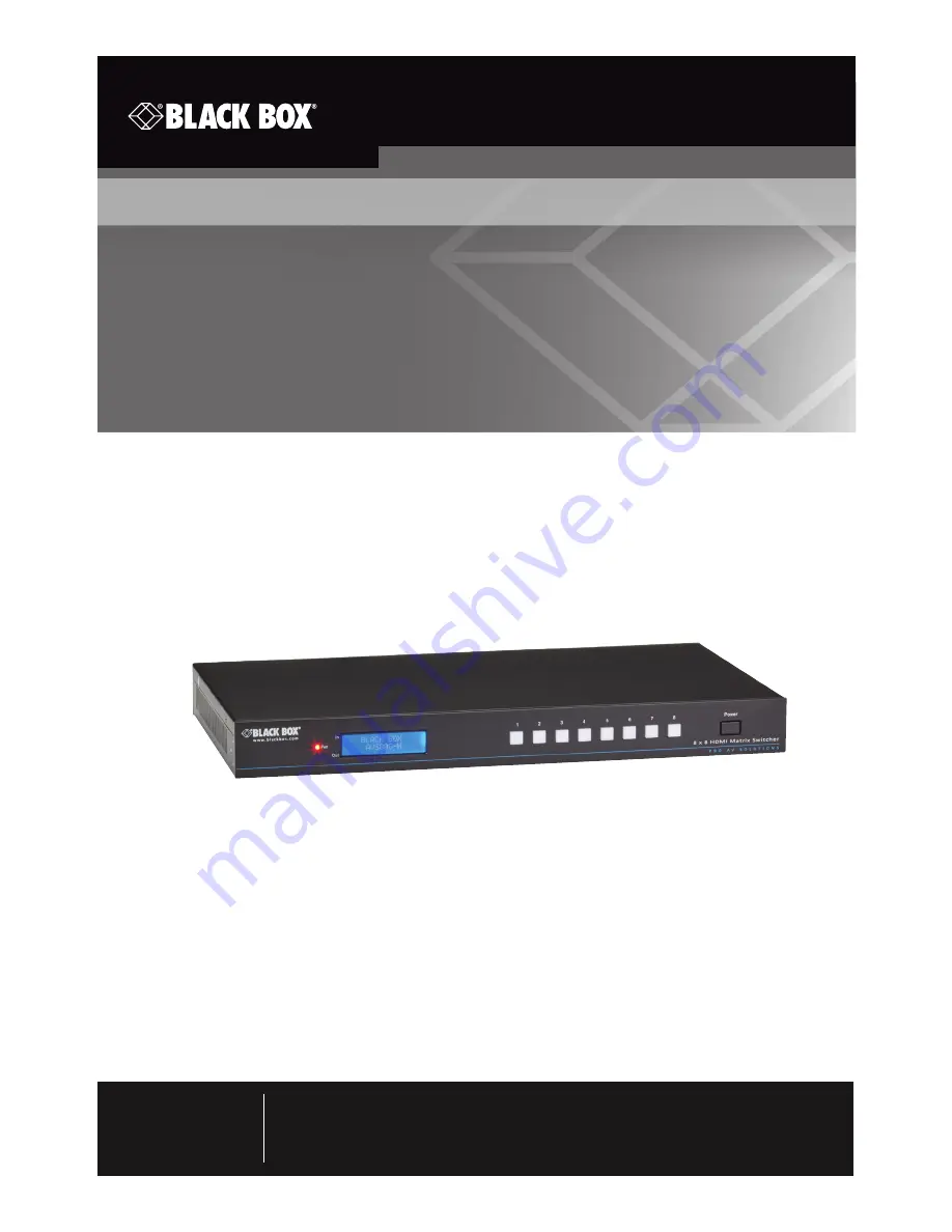
Video Matrix Switcher - 4K, HDMI, Audio, 4 x 4 or 8 x 8

AVS404-H 

AVS808-H

Summary of Contents for AVS404-H

Page 1: ...port 24 7 Call 877 877 BBOX outside U S call 724 746 5500 www blackbox com info blackbox com Contact Information User Manual Switch four or eight HDMI 2 0 and HDCP 2 2 compliant signals Video Matrix Switcher 4K HDMI Audio 4 x 4 or 8 x 8 AVS404 H AVS808 H ...

Page 2: ... Used in this Manual Trademarks Used in this Manual Black Box and the Double Diamond logo are registered trademarks of BB Technologies Inc Any other trademarks mentioned in this manual are acknowledged to be the property of the trademark owners ...

Page 3: ... and on the user is encouraged to try to correct the interference by one of the following measures Reorient or relocate the receiving antenna Increase the separation between the equipment and receiver Connect the equipment into an outlet on a circuit different from that to which the receiver is connected Consult an experienced radio TV technician for help Caution Changes or modifications not expre...

Page 4: ...ue sean recomendados por el fabricante 7 El aparato eléctrico debe ser montado a la pared o al techo sólo como sea recomendado por el fabricante 8 Servicio El usuario no debe intentar dar servicio al equipo eléctrico más allá lo descrito en las instrucciones de operación Todo otro servicio deberá ser referido a personal de servicio calificado 9 El aparato eléctrico debe ser situado de tal manera q...

Page 5: ... caso de existir una antena externa deberá ser localizada lejos de las lineas de energia 16 El cable de corriente deberá ser desconectado del cuando el equipo no sea usado por un largo periodo de tiempo 17 Cuidado debe ser tomado de tal manera que objectos liquidos no sean derramados sobre la cubierta u orificios de ventilación 18 Servicio por personal calificado deberá ser provisto cuando A El ca...

Page 6: ...re shipment Follow basic safety precautions to reduce the risk of fire electrical shock and injury to persons Using supplies or parts that do not meet the products specifications may cause damage deterioration or malfunction Refer all servicing to qualified service personnel Do not place any heavy items on the extension cable Install the device in a place that is properly ventilated to avoid damag...

Page 7: ... System Applications 17 4 Operation 18 4 1 IR Control 18 4 2 RS 232 Control 19 4 2 1 Installing Uninstalling the RS 232 Control Software 19 4 2 2 Basic Settings 19 4 2 3 RS 232 Communication Commands 19 4 3 TCP IP Control 26 4 3 1 Control Modes 26 4 3 2 Control the Switcher via TCP IP Communications Software 28 4 3 3 Control the Switcher via Web Based GUI 28 4 3 4 TCP IP Configuration 39 4 3 5 GUI...

Page 8: ...mission Distance 4K x 2K 60 Hz or to 48 ft 15 m Hardware Connectors AVS404 H Input 4 HDMI Type A female Output 4 HDMI Type A female 4 3 5 mm RCA SPDIF audio Control Ports 1 3 5 mm jack IR IN 1 RJ 45 female TCP IP 1 3 pin pluggable terminal block RS 232 AVS808 H Input 8 HDMI Type A female Output 8 HDMI Type A female 8 3 5 mm RCA SPDIF audio Control Ports 1 3 5 mm jack IR IN 1 RJ 45 female TCP IP 1 ...

Page 9: ... 24 VDC 2 5 A Consumption 32 W full load 2 2 W standby Supported Resolutions Display Ratio Resolutions 4K 4096x2160 30 50 60 Hz 3840x2160 24 25 30 50 60 Hz 21 9 2560x1080 60Hz 16 9 1920x1080 1080P 3D 1600x900 1366x768 1280x720 1024x576 60Hz 16 10 1920x1200 1680x1050 1440x900 1360x768 1 280x800 60Hz 4 3 1600x1200 1400x1050 1280x1204 1024x768 800x600 640x480 60Hz ...

Page 10: ... and 1080p 3D comply with lower HDMI standards and are HDCP 2 2 compatible NOTE This is limited to 4 2 0 in 4K x 2K 60 Hz Transmit 4K x 2K 60 Hz signal up to 48 feet 15 m SPDIF ports provide unembedded HDMI audio output Uses powerful EDID management Controllable via front panel button IR RS 232 and TCP IP LCD screen shows real time I O connection status You can upgrade firmware through a Micro USB...

Page 11: ...ews 1 IR receiver 1 power cord 1 IR remote 2 mounting ears for rackmounting 1 terminal block to DB9 cable 1 24 VDC 2 5 A power adapter 4 rubber feet for desktop mounting This user manual To download this user manual from our Web site 1 Go to www blackbox com 2 Enter the part number AVS404 H or AVS808 H in the search box 3 Click on the Resources tab on the product page and select the document you w...

Page 12: ...nts 1 2 3 4 Figure 2 1 Front panel AVS404 H Table 2 1 Front panel components AVS404 H Number in Figure 2 1 Component Description 1 Power indicator Lights red when power is on Lights green in standby mode Blinks red when upgrading 2 LCD screen Displays real time operation status 3 Output selection buttons Press these buttons to select their corresponding output ports cycles through ports 1 4 4 Powe...

Page 13: ...I audio 3 4 HDMI output ports Connect to HDMI displays 4 Micro USB port Used to upgrade firmware 5 4 position DIP Switch Used to set EDID data 1 stands for ON 0 stands for OFF See Section 4 4 for more details 6 3 pin pluggable terminal block This RS 232 serial port connects to a control device 7 IR IN Input port for IR control signal connects to an IR receiver 8 RJ 45 port RJ 45 port TCP IP port f...

Page 14: ...3 Front panel AVS808 H Table 2 3 Front panel components AVS808 H Number in Figure 2 3 Component Description 1 Power indicator Lights red when power is on Lights green in standby mode Blinks red when upgrading 2 LCD screen Displays real time operation status 3 Output selection buttons Press these buttons to select their corresponding output ports cycles through ports 1 8 4 Power button Press to pow...

Page 15: ...IR receiver 3 3 pin pluggable terminal block This RS 232 serial port connects to a control device 4 4 position DIP Switch Used to set EDID data 1 stands for ON 0 stands for OFF See Section 4 4 for more details 5 Micro USB port Used to upgrade firmware 6 8 3 5 mm RCA SPDIF audio output ports Used for unembedded HDMI audio 7 8 HDMI input ports Connect to HDMI sources 8 8 HDMI output ports Connect to...

Page 16: ... cords are insu lated 3 Connect all devices before powering on 3 2 Connection Diagram Figure 3 1 Connection diagram 3 3 Connection Procedure 1 Connect HDMI sources e g DVD to HDMI INPUTs with HDMI cables 2 Connect HDMI displays e g HDTV to HDMI OUTPUTs with HDMI cables 3 Connect speakers amplifiers to the AUDIO OUTPUTs with audio cables 4 Connect the RS 232 ports of control device e g a PC and Vid...

Page 17: ...er to the IR IN port to enable IR control 7 Plug a 12 VDC power adapter to the power port of Video Matrix Switcher 8 Connect amplifiers that can decode HDMI audio to the SPDIF ports or there will be no output on the amplifiers 3 4 System Applicatiions Use the Video Matrix Switcher for computer monitoring large screen displays conference systems television education and banks etc ...

Page 18: ... users can control it through the included IR remote Here is a brief introduction to the IR remote Figure 4 1 IR Remote Table 4 1 IR remote components Number in Figure 4 1 Component Description 1 Standby Enter exit standby mode 2 Inputs Buttons for input selection 3 Outputs Buttons for output selection NOTE I O Switch Format INPUT OUTPUT ...

Page 19: ...led Double click the software icon to run this software 4 Set the parameters baud rate data bit stop bit and parity bit correctly to ensure reliable RS 232 control 4 2 3 RS 232 Communication Commands NOTE The RS 232 communication commands are case sensitive NOTE in the commands are for easy recognition only and not necessary in real operations Other symbols including are parts of the commands Feed...

Page 20: ...ttons System Unlocked Version Inquire about the firmware version VX X X MessageOff Turn off command feedback from the com port It will only show simple words like SWITCH OK MessageOff MessageOn Turn on command feedback from the com port MessageOn FeedbackON Enable command feedback on LCD monitor on the front panel default FeedbackON FeedbackOFF Disable command feedback on LCD monitor on the front ...

Page 21: ...gnal from input x to all outputs 1 To All All Transfer all inputs to corresponding outputs like 1 1 2 2 All Through x Transfer signal from input x to out put x 1 Through All Switch on all outputs All Open x Switch on output x 1 Open All Switch off all outputs but except coaxial outputs for digital audio All Closed x Switch off output x 1 Closed x B y1 y2 y3 Transfer AV signal from input x to outpu...

Page 22: ...o y EDID y 1 10 12 14 EDIDC3B1 EDIDExtract x y Invoke No y EDID data saved through COM port to input x y 1 10 12 14 Pick up success UpgradeSoftwareEDID y Save the EDID data to No y EDID invoke the EDID by send ing command EDIDExtract x y Please send the EDID file Upgrade success EDIDUpgrade x Upgrade the EDID data of input x x 1 4 upgrade the EDID of single input x 9 upgrade the EDID of all inputs...

Page 23: ...udio part supports not only PCM format then force set it to only support PCM If the EDID data is not available it will set to initial EDID EDIDH1B1 PWON Work normally PWON STANDBY Enter standby mode Return to normal mode via front panel buttons any other command IR remote STANDBY x y Manage HDCP status of out puts x stands for output port can be 1 4 or ALL When x ALL it means manage HDCP status of...

Page 24: ...F audio output of output x x 1 4 enable the SPDIF audio output of single output port x 9 enable the SPDIF audio output of all output ports DigitAudio ON with Output 4 DigitAudioOFF x Disable the SPDIF audio output of output x x 1 4 disable the SPDIF audio output of single output port x 9 disable the SPDIF audio output of all output ports DigitAudio OFF with Output 4 Inquiry Commands Status x Check...

Page 25: ...nnect N Y Y N In 5 6 7 8 Connect N Y Y N 9972 Inquire connection status for all outputs N means there is no display Y means there is connected display Out 1 2 3 4 Connect Y Y N N Out 5 6 7 8 Connect N Y Y N 9973 Check the inputs HDCP status N means it s not with HDCP Y means it s with HDCP In 1 2 3 4 HDCP N Y Y N In 5 6 7 8 HDCP N Y Y N 9974 Check the outputs HDCP sta tus N means it s not with HDC...

Page 26: ...Port cannot be changed Controlled by single PC Connect a computer to the TCP IP port of the Switcher and set its network segment to the same as the default IP of the Switcher 192 168 0 178 Figure 4 2 Modify the IP of PC Controlled by PC s in LAN The Switcher can be connected with a router to make up a LAN with the PC s this makes it able to be controlled in a LAN The Switcher s network segment is ...

Page 27: ...C s network segment to the same as the Switcher Remember the PC s origi nal network segment 3 Set the Switcher s network segment to the same as the router 4 Set the PC s network segment to the original one 5 Connect the Switcher and PC s to the router In the same LAN each PC can control the Switcher asynchronously Then it can control the device via TCP IP communication software ...

Page 28: ...itcher see below 4 3 3 Control Switcher via Web Based GUI The Switcher can also be controlled via web based GUI This allows users to interact with the Switcher through graphical icons and visual indicators Type 192 168 0 178 in your browser The log in interface will appear Figure 4 4 Login GUI This system is divided into administrator and user modes Administrator mode User name admin Password admi...

Page 29: ... Tab Type the user name admin password admin and then click LOGIN The Routing menu Scene tab will appear Figure 4 5 Scene Menu All ten scenes are shown in above interface Select a scene and then click Load to activate the selected scene Click Cancel to cancel the current operation ...

Page 30: ...nnection between every input and output users can carry on the connections by clicking corresponding button Buttons 1 8 at the right bottom corner provide quick saving and recall for overall connection status For example 1 Select button1 at the INPUT column 2 Select button 5 at the OUTPUT column If all OUTPUT ports are needed click All 3 Choose a scene that you want to save 4 Click Confirm to save...

Page 31: ...Page 31 877 877 2269 blackbox com Chapter 4 Operation 4 3 3 3 Routing Menu Audio Tab Click Audio to enter the following interface for intuitive I O connection switching Figure 4 7 Audio tab screen ...

Page 32: ...32 877 877 2269 blackbox com Chapter 4 Operation 4 3 3 4 User Tab To login in user mode type in the user name and password User mode User name user Password user default setting Figure 4 8 Login in user mode ...

Page 33: ...peration 4 3 3 5 Configuration Tab 1 Configuration 1 Click the Configuration button to enter the configuration interfaces Figure 4 9 Embedded EDID All embedded EDIDs of the Switcher are shown in the above interface Select EDID to match your needs ...

Page 34: ...DID of the INPUT device can be copied from OUTPUT devices 1 Select one OUTPUT device that you want to copy its EDID 2 Select one or more input devices that need to gain EDID When selecting To All inputs all input devices will copy the EDID from the output device 3 Click Save to save the setting or click Cancel to cancel the operation ...

Page 35: ...Page 35 877 877 2269 blackbox com Chapter 4 Operation 3 Select Audio Out to enter the following interface to turn on off the Audio Output Figure 4 11 Audio EDID ...

Page 36: ...kbox com Chapter 4 Operation 2 Network 1 At the top of the interface click Network to enter the following interface to modify the name and mode of this machine and then it will display on the LCD screen Figure 4 12 Network Tab ...

Page 37: ...com Chapter 4 Operation 2 Select I O Labels to enter the following interface to modify the name of buttons Figure 4 13 I O labels 3 Select Scene to enter the following interface to modify the name of scenes Figure 4 14 Status Scene ...

Page 38: ...x com Chapter 4 Operation 3 Network At the top of the interface click Network to enter the following interface to inquire and configure network settings including MAC address IP address subnet mask and Gateway Figure 4 15 Network ...

Page 39: ...ect username and password to log in the WebServer Username admin Password admin Here is the main configuration interface of the WebServer Figure 4 16 TCP IP Configuration 4 3 5 GUI Update The GUI for Switcher supports online updating at http 192 168 0 178 100 Type the username and password the same as the GUI log in settings modified password will be available only after rebooting to log in the co...

Page 40: ...sponding RS 232 command Via 4 pin EDID DIP switcher TheVideo Matrix Switcher has a 4 pin EDID DIP switcher to manage EDID Dial the switchers to select EDID data Embedded EDID data 10 sets in total the chart below illustrates the 10 Embedded EDID data Table 4 3 EDID information vis DIP switch Number Switcher Status EDID Information 1 0001 720P 2D 5 1CH 2 0010 720P 3D 5 1CH 3 0011 720P 2D 2CH 4 0100...

Page 41: ...D x 2 Embedded EDID data can also be invoked via command EDID x y 4 5 Firmware Upgrade through USB port The Video Matrix Switcher has a USB port for firmware upgrade on the rear panel Preparation Copy the upgrade software DfuSe Demonstration upgrade file dfu to control PC Follow these steps to upgrade the device 1 Connect the control PC to the USB port of Video Matrix Switcher 2 Reboot Video Matri...

Page 42: ...w will popup Figure 4 19 Upgrade firmware via DfuSe Demonstration 4 Click Choose to load desired upgrade file dfu 5 Click Upgrade to start NOTE Make sure the Leave DFU mode button is available to ensure that the control PC and Video Matrix Switcher are connected successfully ...

Page 43: ... connected and in working order Cause 2 Failed or loose connection Solution 2 Make sure the connection is good Problem No output image when switching Cause 1 No signal at the input output end Solution 1 Check with oscilloscope or multimeter if there is any signal at the input output end Cause 2 Failed or loose connection Solution 2 Make sure the connection is good Cause 3 Input source is HDCP but ...

Page 44: ... output on the amplifiers connected to audio output ports Cause The amplifiers are not able to decode HDMI audio Solution Change to amplifiers that can decode HDMI audio Problem Cannot control the device via front panel buttons Cause Front panel buttons are locked Solution Send command Unlock to unlock Problem Cannot control the device via IR remote Cause 1 Failed battery Solution 1 Replace with a...

Page 45: ... point directly at the IR receiver Problem Power Indicator remains off when powered on Cause Failed or loose power connection Solution Check whether the cables are connected correctly Problem EDID management does not work normally Cause The HDMI cable is broken at the output end Solution Replace with another HDMI cable that is in good working condition Problem There is a blank screen on the displa...

Page 46: ...tion Solution 1 Check to make sure the connection between the control device and the unit is secure Cause 2 Wrong RS 232 communication parameters Solution 2 Type in correct RS 232 communication parameters Baud rate 9600 Data bit 8 Stop bit 1 Parity bit none Cause 3 Broken RS 232 port Solution 3 Contact Black Box Technical Support at 877 877 2269 or info blackbox com Problem Static becomes stronger...

Page 47: ...x com Before you do make a record of the history of the problem We will be able to provide more efficient and accurate assistance if you have a complete description including the nature and duration of the problem when the problem occurs the components involved in the problem any particular application that when used appears to create the problem or make it worse 5 3 Shipping and Packaging If you ...

Page 48: ...nfrastructure products You ll find everything from cabinets and racks and power and surge protection products to media converters and Ethernet switches all supported by free live 24 7 Tech support available in 60 seconds or less Copyright 2016 Black Box Corporation All rights reserved Black Box and the Double Diamond logo are registered trademarks of BB Technologies Inc Any third party trademarks ...

Reviews: