ACS335A KVM-EXTENDER
ACS335A KVM-EXTENDER
ACS335A KVM-EXTENDER
manual :
ftp://ftp.blackbox.com/manuals/ACS/ACS335A_Manual.pdf
manual :
ftp://ftp.blackbox.com/manuals/ACS/ACS335A_Manual.pdf
manual :
ftp://ftp.blackbox.com/manuals/ACS/ACS335A_Manual.pdf
1 Quick Setup
This section briefly describes how to install your KVM extender system and optimise the video
signals. Unless you are an experienced user, we recommend that you follow the full procedures
described in the rest of this manual. The manual can be downloaded from
ftp://ftp.blackbox.com/manuals/ACS/ACS335A_Manual.pdf
2 Installation
For first-time users, we recommend that you carry out a test placement, confined to a single room,
before commencing full installation. This will allow you to identify and solve any cabling problems,
and experiment with the KVM extender system more conveniently.
2.1 Package Contents
You should receive the following items in your extender package:
•
ACS335A KVM-Extender (Local Unit + Remote Unit).
•
VGA CPU cable, ZIP type 1,8m (HD15 male / HD15 female, 2x PS2 male / PS2 male) with
device ACS335A-AS + ACS335A
•
Audio CPU-cable 1,8m (3,5mm Stereo Jack / 3,5mm Stereo Jack) with device ACS335A-AS
•
serial CPU-cable 1,8m (DB9 female / DB9 male) with device ACS335A-AS
•
2x 6V DC universal p.s.u
•
2x power cord.
•
manual (This Quick Setup Guide).
If anything is missing, please contact Technical Support
2.2 System Setup
To install your ACS335A KVM-Extender system:
1.
Switch off all devices.
2.
Connect your keyboard, monitor, mouse, audio device and serial device to the Remote unit
(depending on type of device). Ensure that you attach the keyboard and mouse connectors to
the correct ports. The keyboard connector is purple; the mouse connector is green.
3.
Connect the CPU to the Local Unit, using the supplied CPU cable. Ensure that you attach the
keyboard and mouse connectors to the correct ports. The keyboard connector is purple; the
mouse connector is green.
4.
Connect the 6V power supply to power the unit.
Only use the power supply originally supplied with this
equipment or a manufacturer-approved replacement.
5.
For a dual access system, connect the keyboard, mouse and monitor for the Local console to the
appropriate ports on the Local unit. The ports may also be used to feed into a KVM switch.
6.
Connect the Interconnection cable (Multimode Fibre Cable) from the Remote unit to the
INTERCONNECT socket on the Local unit. Ensure that you attach the fibre connectors to the
correct ports. R goes to R, G to G, B to B, 1 to 1 and 2 to 2.
7.
Power up the system.
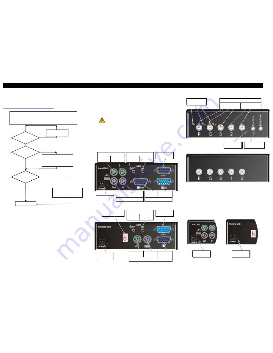
3 Device View (depending on device type)
ACS335A KVM-Extender Local Unit
ACS335A KVM-Extender Remote Unit
ACS335A KVM-Extender Remote Unit
ACS335A KVM-Extender Local Unit
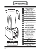
3.1 Diagnostic and Adjustments
Each ACS335A KVM-Extender is fitted with a indicator LED
Device Ready
and a 7-Segment
display for enhanced Trouble Shooting: The
Device Ready
LED’s are next to the Power sockets. The
7-Segment display is next to the Power socket of the remote unit.
On each ACS335A KVM-Extender you can adjust Brightness and Contrast manually. In addition,
each colour can be adopted manually (only with automatic gain control – AGC = OFF). The
Potentiometer to adjust Brightness and Contrast are to the right of the fibre connectors at the remote
unit. The 7- Segment display is next to the Power socket of the remote unit.
The location of the LED’s is shown below:
Install System
1.
Connect Remote unit to KVM.
2.
Connect Local unit to CPU or switch.
3.
Connect Local and Remote units with fibre interconnection cable.
4.
Power up the system.
Done
YES
NO
Does the 7-
segment display show
’0’?
NO
YES
Solve the problem like
described in the ‚Trouble
Shooting’ section.
Wait until the dot
lapses
NO
YES
The fibres for data transmis-
sion (1 + 2) are swapped–
Please switch the fibres at
one device
Is the Dot at the
7 segment display
illuminated?
Does the 7-
segment display show
’C’?
Connect to 6V
Power supply
Connect to CPU
Keyboard socket
Keyboard Connectors
Connect to
local Keyboard
Connect to CPU
VGA- socket
VGA-Monitor Connectors
Connect to
local Monitor
Connect to CPU
Mouse socket
Mouse Connectors
Connect to
local Mouse
Connect to CPU
CPU Line Out
Audio Connectors
Connect to
CPU CPU Line
In
Connect to CPU
V24- socket
Connect to 6V
Power supply
To the serial
device
To the
microphone
Audio Connectors
To the powered
speakers
7-Segment display for
Trouble Shooting
Connect to
remote Keyboard
Console Connectors
Connect to
remote Mouse
Connect to
remote-Monitor
Potentiometer for
Contrast
Connectors for
Digital signals
Fibre connectors (ST)
Connectors for
color signals
Potentiometer for manu-
al gain control
Potentiometer for
Brightness
Diagnostic LED
Device Ready
Diagnostic LED
Device Ready