


◈
Information
This Installation Guide includes a brief outline of information necessary for product installation. For
more detailed installation information, please refer to the user manual in the enclosed CD. The
contents of the CD include the following.
1. Manual: User Manual
2. Drivers: Windows Drivers, OPOS Drivers
We at BIXOLON maintain ongoing efforts to enhance and upgrade the functions and quality of all
our products. In following, product specifications and/or user manual content may be changed
without prior notice.
◈
Components
BCD-1100DN BCD-1100D BCD-1100WN BCD-1100W
Common Components of All Products
CD
Installation Guide
Screws
M3*10, Tapping
(excluding BCD-1100D type)
◈
Connection Type
STEP1. Connect the display cable to a computer via a USB port.
STEP2. Turning on the computer and the power supply unit leads to the automatic detection of the
new hardware connected to the PC via the USB port.
STEP3. Install the USB Virtual COM driver.
STEP4. After driver installation is complete, data can be received.
◈
Rotation Function
This product allows display rotation to any position or angle desired by the user. Please adhere to the
following instructions during installation to prevent possible product damage and/or malfunction. Following
assembly, follow the sequence below to fix the DISPLAY in the desired position.
(a) (b) (c)
(a) Lower the DISPLAY UNIT in the direction of the arrow.
Rotate the NUT-FIX to allow for lowering.
(Please refer to the product OPEN/CLOSE label.)
(b) Rotate the DISPLAY UNIT to the desired angle.
※
Caution
Do not rotate the DISPLAY UNIT in any direction for more that one full revolution.
(Beware as the DISPLAY UNIT can be rotated continuously.)
(c) After setting the DISPLAY to the desired position, secure the NUT-FIX.
(When raising the DISPLAY UNIT, lateral movement is prevented.)
Make sure to tighten the NUT-FIX after raising the DISPLAY UNIT to the desired height.
※
Caution
As excessive tightening of the NUT-FIX can result in product damage and/or
malfunction, secure only to the extent that the DISPLAY UNIT is fixed and does not
move.
※
Caution
As shown in figure (A), make sure to fully lower the DISPLAY UNIT before rotating.
Rotation of the DISPLAY UNIT when it is not fully lowered will produce a clicking
sound. This sound does not indicate any product breakage and is a result of the friction
between the POLE-MAIN RIB and the rotation section within the POLE-ADJUST.
◈
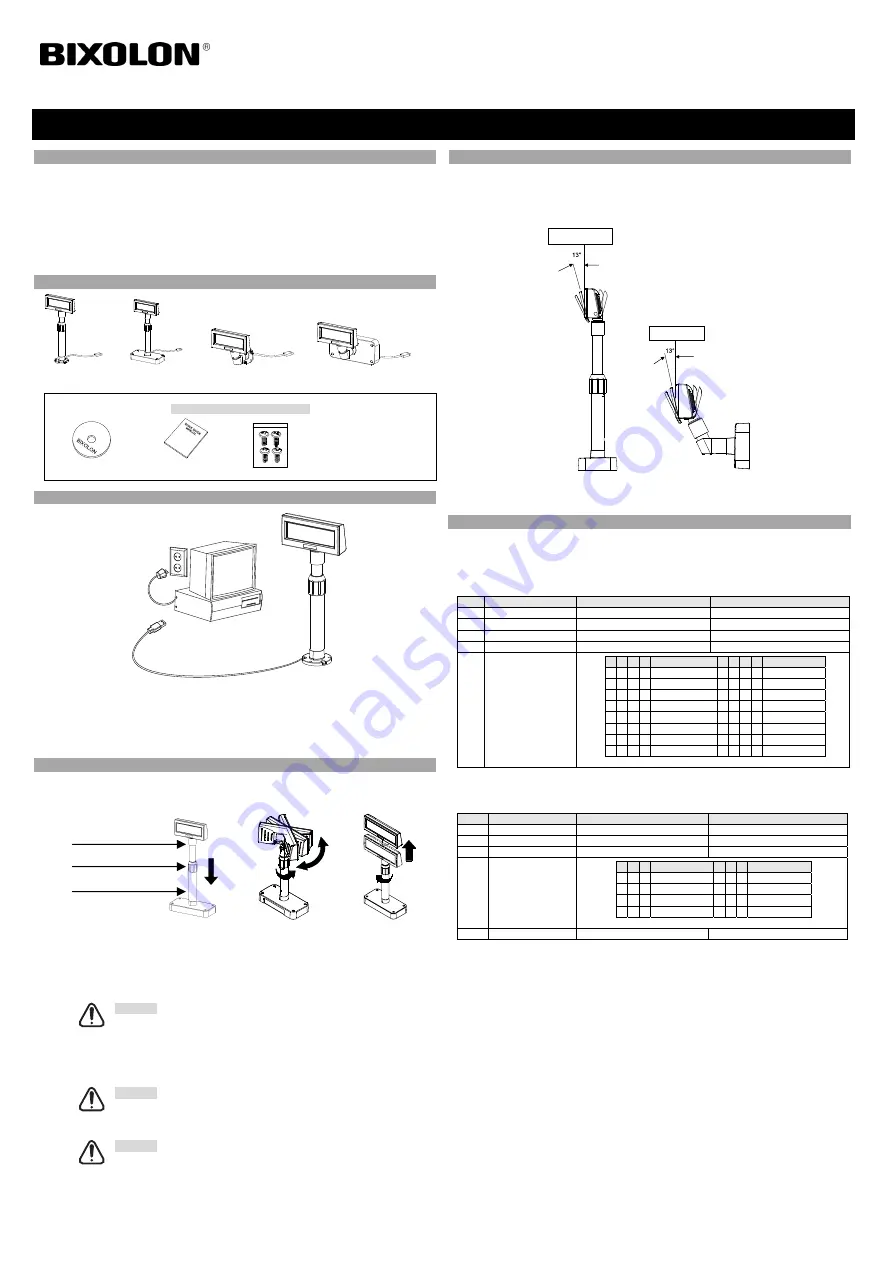
Tilting Function
This product allows display tilting to any angle desired by the user. Please adhere to the following
instructions during installation to prevent possible product damage and/or malfunction. The display
can be angled left and right from the Center Line in 13° angle intervals for a total of 4 steps, 5
positions. (Angling: 52°max.)
◈
Setting the DIP Switches
DIP switch settings can be read only when the power is on.
Therefore, any changes to the settings when the power is on do not take effect
.
1. DIP Switch #1 Function (RS-232 Serial Input Setting)
No.
Function
Switch OFF
Switch ON
1
Default Setting
DIP Switch Values
EEP-ROM Data Leading
2 Reserved
-
-
3
Display Vewing Side
Customer Side
Operator Side
4
Self-Test Execution
Does not execute
Executes
5~8
Emulation
5 6 7 8
Emulation
5 6 7 8
Emulation
0 0 0 0 Samsung VFD 1 0 0 0 NCR Real POS
0 0 0 1 Epson ESC/POS 1 0 0 1
PD6000
0 0 1 0 ADM787/788 1 0 1 0
ICD2002
0 0 1 1
DSP800
1 0 1 1
Reserved
0 1 0 0
AEDEX
1 1 0 0
Reserved
0 1 0 1 UTC Standard 1 1 0 1
Reserved
0 1 1 0 UTC Enhance 1 1 1 0
Reserved
0 1 1 1
CD5220
1 1 1 1
Reserved
(“0” : S/W OFF, “1” : S/W ON)
2. DIP Switch #2 Function
No.
Function
Switch OFF
Switch ON
1
Data Length
8 Bits
7 Bits
2
Parity using
None Parity
Parity
3 Parity
Selection
Odd
Even
4~6
Transmit Speed
4 5 6 Transmit Speed 4 5 6 Transmit Speed
0 0 0
9,600 bps
1 0 0
115,200 bps
0 0 0
4,800 bps
1 0 1
57,600 bps
0 1 1
2,400 bps
1 1 0
38,400 bps
0 1 0
1,200 bps
1 1 1
19,200 bps
(“0” : S/W OFF, “1” : S/W ON)
7~8
Reserved -
-
Display Installation Guide
KN10-00004A (Rev.1.2)
CUSTOMER DISPLAY BCD-1100
Center Line
Center Line
Pole-Adjust
Nut-Fix
Pole-Main


