background image

Bholanath

COMMITTED TO PRECISION

®

www.bholanath.in

Email : [email protected]

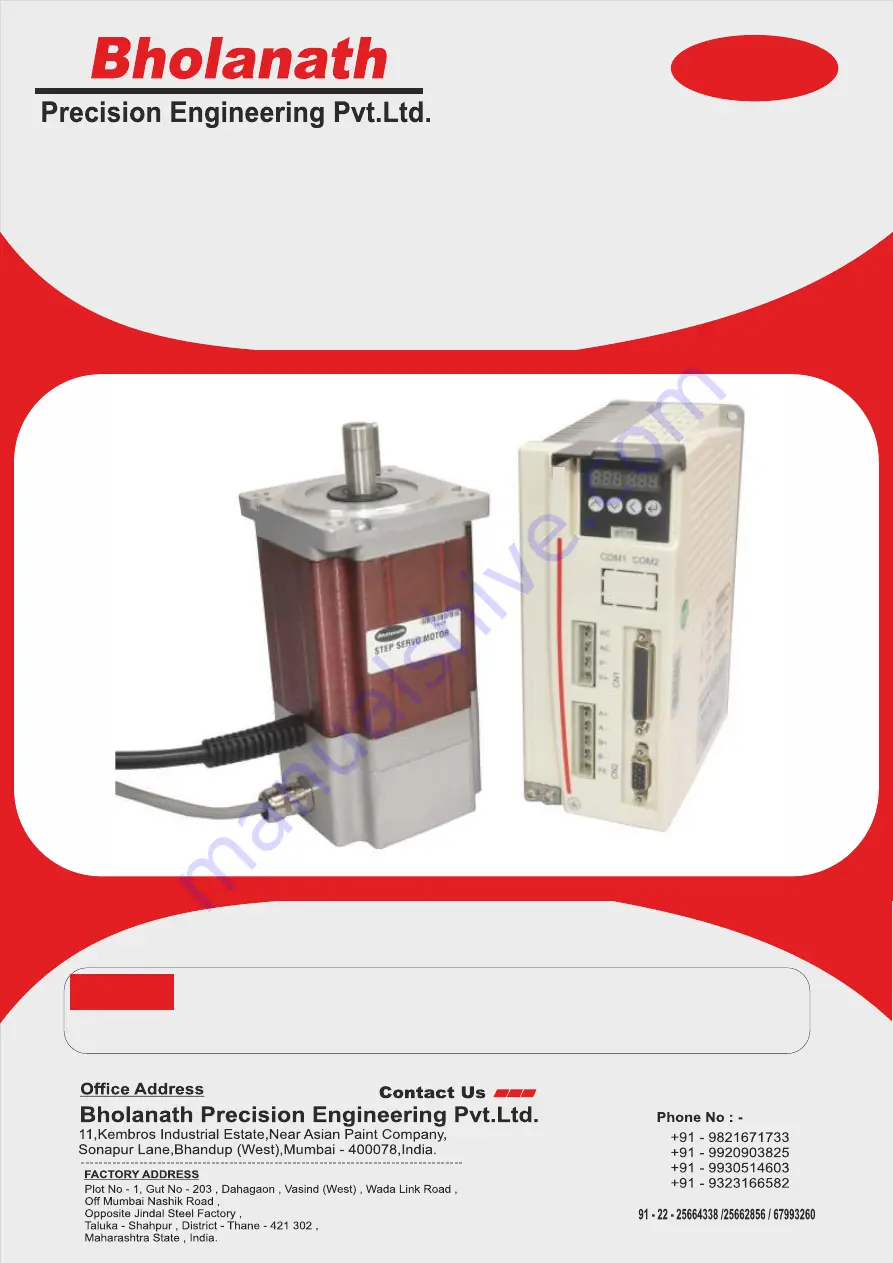
 Parameter Setting Drive Step servo  & motor are 
 matched pair with 

BH-

110VAC power supply

Note:-

Parameter Setting & High Torque Step Servo

BHSS - 1000W-PARA

User’s Manual

BHOLANA

TH

BHSS-1000W

-PARA

Summary of Contents for BHSS-1000W-PARA

Page 1: ...N www bholanath in Email support bholanath in Parameter Setting Drive Step servo motor are matched pair with BH 110VAC power supply Note Parameter Setting High Torque Step Servo BHSS 1000W PARA User s Manual BHOLANATH BHSS 1000W PARA ...

Page 2: ... and motor output port 8 4 2 2 Encoder feedback port 9 4 2 3 Control signal port 9 4 2 4 Status Indicator 10 4 2 5 Button X4 10 5 Menu Operation 11 5 1 Operation interface 11 5 2 Menu introduction 11 5 2 1 System monitor menu items dP 12 5 2 2Parameter setting menu PA 13 5 2 3 Parameter management menu EE 17 5 2 4 Internal test menu item Sr 18 5 2 5 History fault display dE 18 6 Encoder Cable Spec...

Page 3: ...ised to consider safety precautions during use to prevent accidents caused by improper operation or product abnormalities Due to product improvements the contents of this manual are subject to change without notice Our company will not be responsible for any modification of the product by the user When reading please pay attention to the following signs in the manual Notice Remind you to pay attent...

Page 4: ...ith Electro Magnetic Brake BR With Helical Gearbox HL CE Certificate N STANDARD CE CERTIFIED BHSS 400 W S 1000 3MTR IP 60 N ORDERING CODE Closed Loop Stepping System which includes High Speed 2000 RPM Stepper Motors with Incremental Optical Encoders Digital Drives and 3 Meter Cable SUITABILITY The BHSS 1000 W PARA Step Servo is comparable to 400 Watts Servo Motor upto 600RPM The Step Servo Motor B...

Page 5: ...error overvoltage and position deviation error l 6 digital LED display which can easily set parameters and monitor motor running status l Pulse command averaging filter the filter can turn the curve without acceleration and deceleration into a trapezoidal acceleration deceleration curve which greatly smoothes the motion The trapezoidal acceleration deceleration curve is filtered to become a smoother ...

Page 6: ... Pulse Frequency 500 MΩ 2 2 Working Environment Cooling Method Natural cooling or external heat sink Working Environment Working occasion Keep away from other heating equipment as far as possible to avoid dust oil mist corrosive gas strong vibration flammable gas and conductive dust Temperature 0 C 50 C Humidity 40 90 RH Vibration 5 9 m s 2 Max Storage Temperature 20 C 80 C Weight Around 1000g Bhol...

Page 7: ...urface of the heat sink if necessary install a fan near the drive to force heat dissipation to ensure that the drive works within a reliable operating temperature range The reliable operating temperature of the drive is usually within 60 C and the motor operating temperature is within 80 C Bholanath COMMITTED TO PRECISION www bholanath in 168 180 76 64 6 139 2 BHSS PTR Input supply Voltage 110VAC ...

Page 8: ...wer input port and motor output port No Symbol Name Definition 1 AC Power input port Connect 110V AC 2 AC 3 A Motor power port Connect motor Green line 4 A Connect motor Black line 5 B Connect motor Red line 6 B Connect motor Blue line Status indica on interface Control signal port Button X4 Encoder input port Power input port Motor output port Bholanath COMMITTED TO PRECISION www bholanath in 8 IN...

Page 9: ...sitive input Direction signal input signal 6 DR Direction negative input 21 24DR Direction 24V positive input 11 5MF Enable 5V positive input Enable signal input signal 12 MF Enable negative input 27 24MF Enable 24V positive input 13 5CLR_A Deviation clear 5V positive input Deviation clear signal input signal 14 CLR_A Deviation clear negative input 29 24CLR_A Deviation clear 24V positive input 9 P...

Page 10: ...ents as shown in the following figure 4 2 4 Status Indicator PARA has a 6 digit LED to display the status When the drive fails the drive will stop and show corresponding fault code the drive will save the latest fault in the EEPROM of the drive according to the queue form and the drive can save up to 10 latest history failure 4 2 5 Button X4 button display panel to implement the functions of up dow...

Page 11: ...key to return to the previous menu or cancel the operation confirm Enter the next menu or to confirm the operation 5 2 Menu introduction There are three levels for system menu Level 1 menu contains 5 item the menu items can be switched up and down by button up page and button down page Press confirm button once to go to the next menu Long press to return to the previous menu Short press on other menu...

Page 12: ... low 4 bit Encoder pulse number dP PoS Current position high 4 bit Encoder pulse number dP CPo Position command low 4 bit Command pulse number dP CPo Position command high 4 bit Command pulse number dP EPo Position deviation low 4 bit Encoder pulse number dP EPo Position deviation high 4 bit Encoder pulse number dP I Motor current mA dP bUS Drive internal bus voltage V dP Err Error code 00 No erro...

Page 13: ...menu item corresponds to a system parameter By press and to select the parameter that you want to set then press to enter parameter setup interface In the process of setting parameters short press to shift by press and to modify the value the values displayed will not be applied immediately only after the user press button the values displayed are effectively applied to system When you need to exi...

Page 14: ...er motor microstep 1600 1 60000 PA 8 Encoder resolution 4000 4000 PA 9 Tracking error alarm threshold This value can be changed based on actual need 5000 0 65535 encoder pulses PA 10 Current loop Kp 1817 0 65535 PA 11 Current loop Ki 50 0 65535 PA 12 Current loop Kc 256 0 65535 PA 13 Alarm clear signal CLR A function selection 0 CLR A to clear deviation alarm 1 CLR A to change the direction of the...

Page 15: ...command when the position deviation is less than the number of encoder pulses set by PA 23 it is in position 2 No position command and the position deviation is less than the number of encoder pulses set by PA 23 output in position signal until the time set in PA 24 in position hold time in milliseconds is passed After the holding time of the in position signl the status is determined by the posit...

Page 16: ...3 when the operation mode is self running or when the Sr ON internal test menu is executed 50 0 65535Hz PA 46 Acceleration time 50 0 65535ms PA 47 Deceleration time 50 0 65535ms PA 48 Target speed 1600 0 65535 Hz PA 49 Running pulse number high 2 bytes 0 0 20000 PA 50 Running pulse number low 2 bytes 1600 0 65535 pulse PA 51 Intermittent time 100 0 65535ms PA 52 Repeat time 10 0 65535 times PA 53 ...

Page 17: ...ious value after re power EE rd Parameters read read EEPROM parameter data into memory EE bA Parameter backup write parameters from drive memory to EEPROM backup area EE rS Restore the backup to memory This operation does not write parameter to EEPROM parameter area If users want to permanently use EEPROM backup zone data you need to perform write operation EE SEt EE dEF Restore the default value ...

Page 18: ...ternal test ends and the motor stops running 5 2 5 History fault display dE To view the latest 10 history of faults saved in drive EEPROM Level 1 menu Level 2 menu Function dE History fault check dE 1 Displays the latest fault code in dE 01 Displays the second latest fault code in dE 02 dE 2 dE 3 dE 4 dE 5 dE 6 dE 7 dE 8 dE 9 dE 10 Bholanath COMMITTED TO PRECISION www bholanath in 18 INDEX ...

Page 19: ...ws the encoder cable size drawing The standard encoder cable length is 2m and other specifications such as 3m 4m 5m 8m 9m 10m 12m 14m are available D B 15P Encoder Wiring 1 2 3 4 5 6 7 8 9 1 Red EA 2 Green EA 3 Brown EB 4 Yellow EB 5 White 5VCC 6 Black EGND Bholanath COMMITTED TO PRECISION www bholanath in 19 INDEX ...

Page 20: ...e within the voltage range required by the drive Is the power input connected Is the connec on loose Is the connec ng part loose disconnected broken or shorted Is the wiring correct Is the control signal port wiring correct Is the connec ng part off disconnected or shorted Is the encoder feedback port loose or disconnected Is the connec on loose Does the motor have an abnormal sound Does the electr...

Page 21: ...onnected as required Check if the motor current line is shorted Err 4 Encoder error Encoder feedback interface is loose off line disconnected shorted The motor components are damaged Drive failure Check that the encoder feedback cable is correct and connected reliably Replace a new motor Replace a new drive Err 7 Tracking tolerance error protection Motor current line A A B B is not reliably connec...

Page 22: ...e drive Err 1 Drive memory read error The drive is powered off before parameter save completed The data in the drive parameter save area is damaged Drive failure Execute EE dEF to restore the factory defaults of the drive and eliminate the fault Execute EE dEF to restore the factory defaults of the drive and eliminate the fault Replace a new drive Bholanath COMMITTED TO PRECISION www bholanath in ...

Reviews: