background image


RGT-SQ02-wifi 

Professional Weather Station 

User Manual 


1. Introduction 

Thank you for your purchase of the RGT-SQ02-wifi 

Professional WIFI Wireless Weather sta-

tion

. The following user guide provides step by step instructions for installation, operation and 

troubleshooting. 

2. Warnings 

Warning: 

Any metal object may attract a lightning strike, including your weather station 

mounting pole. Never install the weather station during a storm.  

Warning: 

Installing your weather station in an elevated location may result in injury or 

death. Safety goes first. Make sure your setup and preparation is secure, and take no risks. 

3. Getting Started 

The RGT-SQ02-wifi weather station consists of a display console (receiver), a sen-
sor array with Integrated Outdoor Transmitter and mounting hardware. 


Parts List 

The RGT-SQ02 weather station consists of the following parts (as referenced in Figure 1 ).  
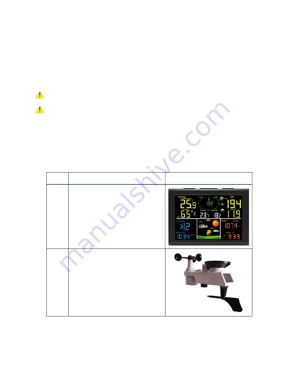
QTY


Item


Image


Display Console


Frame Dimensions (LxHxW): 
135X26X96mm 
LCD Dimensions (LxW): 111 x 75mm 


Integrated Outdoor Transmitter 
Dimensions (LxHxW)

330x150x280mm 


Summary of Contents for RGT-SQ02

Page 1: ... during a storm Warning Installing your weather station in an elevated location may result in injury or death Safety goes first Make sure your setup and preparation is secure and take no risks 3 Getting Started The RGT SQ02 wifi weather station consists of a display console receiver a sen sor array with Integrated Outdoor Transmitter and mounting hardware Parts List The RGT SQ02 weather station co...

Page 2: ...th pole insert Dimensions 84x 152 x 216mm 1 Mounting Bracket Back Plate pole mount Dimensions 76 x 102 x 38mm 1 Mounting Pole Dimensions 76 x 76 x 25mm 2 Pole mounting nuts M3 bolts Ø3 4 Pole mounting nuts M5 bolts Ø5 4 Tapping screws ...

Page 3: ...l Phillips screws Compass or GPS for wind direction calibration Adjustable Wrench Hammer and nail for hanging remote thermo hygrometer transmitter 3 3 Setup of Sensor The following illustration shows the full segment for Thermo Hygrometer WIND RAIN and UV INDEX sensor purposes only as shown in Figure 2 ...

Page 4: ...s into the transmitter Locate the battery cover on the transmitter push and open the battery compartment as show in Figure 3 Figure 3 Remove the battery cover on the back of the sensor by removing the set screw as shown in Figure 4 ...

Page 5: ...ake sure the gasket around the battery compartment is properly seated in its place prior to closing the door Tighten the set screw Note Do not install the batteries backwards You can permanently damage the sensors The solar panel does not charge the batteries so rechargeable batteries are not needed or rec ommended ...

Page 6: ...the battery cover and push it to close the compartment Note If the sensor does not power up after inserting the batteries press the reset button shown in Figure 6 Figure 6 3 4 Display Console 3 4 1 Display Console Layout The display console layout is shown in Figure 7 Note The following illustration shows the full segment LCD display for description pur poses only and will not appear like this dur...

Page 7: ...date and year 15 Rainfall units of measure 16 Rainfall HI alarm icon 17 Rainfall display RATE 24h WEEK MONTH TOTAL 18 Wind speed average display 19 Wind gust display 20 Wind speed units of measure 21 Feels like HI Lo alarm icon 22 Wind direction 23 Dew point and AT Apparent Tempera ture display icon 24 Integrated outdoor transmitter Low pow er indicator 25 Out Indoor temperature units F or C 26 Ou...

Page 8: ...e Figure 8 Replace the battery case and fold out the desk stand and place the console in the upright posi tion The unit will instantly display indoor temperature humidity tendency and time The wind speed wind gust wind direction rain UV Sunlight Integrated outdoor temperature and hu midity will update on the display within a few minutes Do not Press any menu buttons until the outside transmitter r...

Page 9: ...DC jack on the left as shown in Figure 13 Figure 13 2 Insert the DC plug correctly as shown in Figure 14 Figure 14 3 If you want to put it on a table or cabinet opened the desk stand and turn the DC plug up until 90 degrees as shown in Figure 15 ...

Page 10: ...ding on the dis play console is not reading 0 00 Each click represents 0 3mm of rainfall 2 Verify proper operating of the wind speed Rotate the wind cups manually or with a constant speed fan Verify the wind speed is not reading 0 0 3 Verify proper operation of the indoor and outdoor temperature Verify the indoor and out door temperature match closely with the console and sensor array in the same ...

Page 11: ...g there are no interfering obstacles such as build ings trees vehicles high voltage lines Wireless signals will not penetrate metal buildings Most applications will only reach 30m due to building obstructions walls and interference 5 Radio interference such as PCs radios or TV sets can in the worst case entirely cut off ra dio communication Please take this into consideration when choosing console...

Page 12: ...or the Northern Hemisphere only Step 1 There is a S indicator on the wind vane that indicates South as shown in Figure 13 Align this S marker in the direction of South Step 2 Console operation is set to Northern Hemispheres NOR in the time area in Location division Note There are four alphabet letter of N E S and W around the wind direction representing for the direction of North East South and We...

Page 13: ...solar panel North Step 2 Console operation is set to Southern Hemispheres SOU in the time area in Location division Note Console has to be location division setting so that the directions on the sensor are matching with your real location Permanent wind direction error read approximately 180º will be introduced when the wind direction sensor is not positioned correctly during installa tion Fasten ...

Page 14: ...Figure 14 Tighten the mounting pole to your existing mounting pole with the four 5 Bolts and M5 Nuts assembly or fix on the wall with four tapping screw as shown in Figure15 ...

Page 15: ...Figure 15 ...

Page 16: ... the CHANNEL or MIN MAX key to toggle between time date and year 2 Indoor Temperature Press the CHANNEL or MIN MAX key to toggle between out indoor for temperature and humidity alarm on off view 3 Rainfall Press the CHANNEL or MIN MAX key to toggle between rate 24h week month and total To clear the total rain press the CHANNEL or MIN MAX button until total rain is dis played The total rain will fl...

Page 17: ...o change the temperature units of measure the UNITSET icon will be displayed Press the key or key to switch between F and C units of measure 11 Wind Speed Units of Measure default m s Press the SET key again to change the wind speed units of measure Press the key or key to toggle the wind speed units be tween m s ft s bft knots mph or km h 12 Rainfall Units of Measure default mm Press the SET key ...

Page 18: ...me area to clear all min values Indoor and out temperature and humidity minimum values The mini mum values will now display the current values Press the SNOOZE key to exit the min max checking and cleaning mode return to normal display mode 7 6 Snooze Mode If the alarm sounds and you wish to silence the alarm press the SNOOZE key the backlight will turn on The alarm icon will continue to flash and...

Page 19: ...d audible To silence the beeper press any key 8 2 Viewing the High and Low Alarms To view the current alarm settings press the ALARM key to enter the alarm mode ALARM will be displayed in the time area At the same time Alarm time parameters of out indoor tem perature humidity rain rate AT feels like wind gust wind average and dew point are dis played Press ALARM key again to view the LOW alarms al...

Page 20: ...24h high alarm 17 Indoor temperature high alarm 18 Indoor temperature low alarm 19 Indoor humidity high alarm 20 Indoor humidity low alarm Note To prevent repetitive temperature alarming there is a 0 5 C tolerance band For ex ample if you set the high alarm to 26 7 C and silence the alarm the alarm icon will continue to flash until the temperature falls below 26 2 C at which point the alarm will r...

Page 21: ...icon will appear on the LCD The time will automatically synchronize to the internet per an hour Note Time synchronize method Synchronized through internet UTC time serv er WiFi Connection and Weather Servers 11 Register with WeatherCloud net Note This is best done on a computer desktop or laptop Visit https weathercloud net and enter a Username Email and Password It is your Login password of the w...

Page 22: ...w an email will be received in your registered mailbox Figure 19 4 As shown below open your mail and log in to the Web address in the mail Figure 20 5 As shown below click here to enter the homepage of the weathercloud website ...

Page 23: ...Figure 21 6 As shown below enter the email address and password you just registered to enter the weathercloud website Figure 22 11 2 Add a weather station device it may take a few minutes ...

Page 24: ...Create device and enter your station s information Blanks with red must be filled in Figure 24 Note You can select any Model number and Link type in the above blanks 2 As shown below click Get coordinates to identify your location of on the map then click Done to confirm ...

Page 25: ...Figure 25 3 As shown below click Create Figure 26 4 As shown below after registering successfully please record the Weathercloud ID and Key information for later use Refer to 13 6 Figure 27 ...

Page 26: ...t https Wunderground com and select the Join link in the upper right and corner and create a Free Account 1 as shown below Click Join Figure 28 2 As shown below enter a Username Email and Password It is your Login password of the websiteIt not your email password So no privacy will be exposed Click Sign up for free ...

Page 27: ...Figure 29 3 As shown below registration is done successfully Figure 30 4 As shown below click Log in and enter the email address and password you just regis tered ...

Page 28: ...Figure 31 5 As shown in the below click My Profile Then enter Member Settings Figure 32 6 As shown below click Update home location ...

Page 29: ...Figure 33 7 As shown below you will then be prompted to add a device Select Add New Device Figure 34 8 As shown below click Personal Weather Station Figure 35 ...

Page 30: ...on your address automatically Then click Next Figure 36 10 As shown below you will then be prompted to add a device Select Create device then click I Accept and Next Blanks with red Required must be filled in Note You can select any wifi weather station model in Device Hardware blank ...

Page 31: ...re 37 11 As shown below after registering the host successfully please record Station ID and Station Key information for later use refer to 13 6 Figure 38 12 As shown below registration is done successfully ...

Page 32: ...ablet or smart phone to connect to the console s WiFi The console s network name begins with WeatherHome followed by a unique code Note that when the console programming is complete you will resume your default WiFi connection Note that you cannot connect two or more devices at the same time when WAP mode 13 1 Example 1 Connect to the console WiFi server with a PC Choose WiFi network settings from...

Page 33: ...igure 41 your WiFi network name may be slightly different but will always begin with WeatherHome Figure 41 13 3 Example 3 Connect to the console WiFi server with an iPhone or iPad Choose the Settings icon and Wi Fi Connect to the WeatherHomeWiFi network as shown in Figure 42 your WiFi network name may be slightly different but will always begin with WeatherHome ...

Page 34: ...ttings icon and Wi Fi Connect to the WeatherHome WiFi network as shown in Figure 43 your WiFi network name may be slightly different but will always begin with WeatherHome Figure 43 13 5 Once connected enter the following IP address into any browser s address bar http 192 168 5 1to access the console s web interface ...

Page 35: ...ader http or http 192 168 5 1 not 192 168 5 1 13 6 Enter the following information into the web interface Figure 44 Make sure all of the information is entered prior to selecting Save If you choose not to upload Wunderground com or upload weathercloud net leave the check boxes unchecked ...

Page 36: ...Mean Time GMT The following table provides times zones throughout the world Locations in the eastern hemi sphere are positive and locations in the western hemisphere are negative Hours from GMT Time Zone Cities 12 IDLW International Date Line West 11 NT Nome Nome AK 10 AHST Alaska Hawaii Standard CAT Central Alaska HST Hawaii Standard Honolulu HI 9 YST Yukon Standard Yukon Territory ...

Page 37: ...il 2 AT Azores Azores Cape Verde Is lands 1 WAT West Africa 0 GMT Greenwich Mean WET Western European London England 1 CET Central European Paris France 2 EET Eastern European Athens Greece 3 BT Baghdad Moscow Russia 4 Abu Dhabi UAE 5 Tashkent 6 Astana 7 Bangkok 8 CCT China Coast Bejing 9 JST Japan Standard Tokyo 10 GST Guam Standard Sydney 11 Magadan 12 IDLE International Date Line East NZST New ...

Page 38: ... Wi Fi console s status Wi Fi icon will stop flashing and remain on NOTE When the console successfully connects to your any website of weather servers the data signal icon will appear on the LCD display behind the In Outdoor humidity If the data signal icon is flashing the console is currently uploading to the server If the icon dis appears the console is not connected to the weather server for mo...

Page 39: ...e You may get the latest firmware of the console as below 14 1 When you first power up AC the console or press and hold the MIN MAX WiFi but ton for three seconds in normal mode the console icon behind the In Outdoor humidity will flash to signify that it has entered WAP wireless access point mode and is ready to enter for WIFI settings 14 2 Use your smart phone tablet or computer to connect to th...

Page 40: ...s figure 50 Figure 50 14 6 If update successfully when press Upgrade key Then you will see the following Figure 51 NOTE In this upgrade only Wifi firmware is updated The console does not reset 14 7 Once the upgrade is completed the console will automatically exit WAP mode ...

Page 41: ...nges in the next 24 to 48 hours and varies from location to location The tendency is simply a tool for projecting weath er conditions and is never to be relied upon as an accurate method to predict the weather 15 2 Weather Icons Condition Icon Description Sunny Pressure is rising and the previous condition is partly cloudy Partly Cloudy Pressure is falling and the previous condition is sunny or Pr...

Page 42: ...eat Index and Wind Chill At temperatures less than 4 4C the wind chill is displayed as shown in the WeatherLine Service Wind Chill Table below Figure 52 At temperatures greater than 26 7C the heat index is displayed as shown in the WeatherLine Service Heat Index Table below ...

Page 43: ...ur default level 2 mbar hour The lower the level pressure threshold setting the higher sensitivity for weather forecast changes Locations that experience frequent changes in air pressure require a higher setting compared to locations where the air pressure is typically stagnant 16 6 Restore Factory Default To restore the console to factory default WiFi network Weather server and display press the ...

Page 44: ...Accuracy Resolution Indoor Temperature 0 to 60 C 1 C 0 1 C Outdoor Temperature 40 to 60 C 1 C 0 1 C Indoor Humidity 10 to 99 5 only guaranteed between 20 to 90 1 Outdoor Humidity 10 to 99 5 only guaranteed between 20 to 90 1 UV Index 1 to 15 1 1 Sunlight 0 to 200klux 15 15 Rain 0 to 9999mm 15mm 1 mm 15mm to 9999mm 7 1000mm 0 3mm 1000mm 1mm Wind Direction 0 360 º 10º 16 point compass 1º 16 point co...

Page 45: ...e lithium batteries in cold weather climates less than 20 C 16 4 WiFi Specifications 1 WIFI Standard 802 11 b g n 2 WiFi Console RF Frequency 2 4 GHz 3 Setup User Interface UI support setup device Build in WiFi with WAP mode smart de vice including laptops computers smart phones and smart pads 4 Recommend web browser for setup UI Web browser support of HTML 5 such as the latest versions of Chrome ...

Page 46: ... 5m move the sensor assembly away from the display console Make sure the remote sensor LCD display is working and the transmitter light is flashing once per 60 seconds Install a fresh set of batteries in the remote thermo hygrometer For cold weather environments install lithi um batteries Make sure the remote sensors are not transmitting through solid metal acts as an RF shield or earth barrier do...

Page 47: ...oes not display on console Check your router for problems 1 Check WiFi symbol on the display If wireless connectivity is successful the WiFi icon will be displayed in the time field 2 Make sure your modem WiFi settings are correct network name and password 3 Make sure the console is plugged into AC power The console will not connect to WiFi when powered by batteries only 4 The console only support...

Page 48: ...haracter a limitation of Wundeground com not the station Example worknet is not a valid pass word but worknet is valid 2 Confirm your station ID is correct 3 Make sure the date and time is correct on the console If incorrect you may be re porting old data not real time data 4 Make sure your time zone is set properly If incorrect you may be reporting old da ta not real time data 5 Check your router...

Reviews: