background image

Providing sustainable energy solutions worldwide

178 028 82-1    2015-11-20

Installation- and maintenance instruction

BG550/BG650

Modell 2, M

Summary of Contents for BG550 Series

Page 1: ...Providing sustainable energy solutions worldwide 178 028 82 1 2015 11 20 Installation and maintenance instruction BG550 BG650 Modell 2 M...

Page 2: ......

Page 3: ...___________ 32 8 5 MULTI BLOC MB VEF 412 415 B01 ______________________ 33 8 6 MULTI BLOC MB VEF 420 425 B01 ______________________ 34 8 7 Technical data_______________________________________________...

Page 4: ...utput range The burner must be installed so that it complies with local regulations on ire safety electrical safety and boiler and fuel distribution Make sure when installing the equipment that enough...

Page 5: ...allation work has been completed and approved the electrical installation has been carried out properly the correct fuses added to circuits and measures to safeguard enclosures on electrical devices a...

Page 6: ...er rooms which are specially designed to provide protection against the starting and spreading of ire and the production and spreading of combustion gas Swedish building regulations BFS 2011 26 Separa...

Page 7: ...rner The surface temperature of the burner s components may exceed 60 C Be careful when servicing there may be a risk of pinching Ensure that the burner is protected against direct spraying of water s...

Page 8: ...tube measure B Burner tube measure C BG 550 Standard 1 256 226 162 162 Standard 2 356 326 Standard 3 456 426 BG 650 Standard 1 316 286 185 162 Standard 2 416 386 Standard 3 516 486 Depending on which...

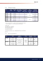
Page 9: ...derlying calculation in normal ambient conditions 15 C 1013 25 mbar as per SS EN 676 Caloriic value G20 Natural gas 10 0 kWh Nm3 G25 Natural gas 8 0 kWh Nm3 G31 Propane 26 kWh Nm3 G30 Butane 34 kWh Nm...

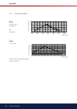
Page 10: ...Pressure in ire place 2 100 200 300 400 500 600 700 2 0 6 8 10 12 14 4 200 300 400 500 600 700 800 2 0 6 8 10 12 14 4 2 900 1000 1100 1200 1 3 Working field BG550 G20 G30 G31 140 628 kW G25 140 608 kW...

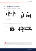
Page 11: ...P1 L1 MP N 2 1 2 1 1 Electritrical connection MB DLE403 B01 2 Skeleton diagrams 2 1 Multi Bloc MB DLE403 B01 When Bio gas is used Bentone shall always be contacted 1 2 pe 3 pa 2 pe 3 pa 4 1 3 2 2 3 1...

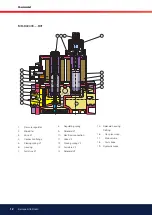
Page 12: ...2 Microilter 3 Valve V1 4 Connection lange 5 Closing spring V1 6 Housing 7 Armature V1 8 Regulating spring 9 Solenoid V1 10 Electrical connection 11 Valve V2 12 Closing spring V2 13 Armature V2 14 Sol...

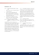
Page 13: ...g 8 tension spring via setting screw 16 The output pressure acts via opening E on the working diaphragm of regulator part 1 In regulated state setting spring inlet pressure and pressure of working dia...

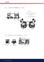
Page 14: ...4 4 5 S 22 S 52 Valves V1 V3 1st stage Valve V2 2nd stage P1 L1 P2 L2 Mp N N Mp L P N Mp L P P2 L2 P1 L1 MP N 1 2 3 2 2 1 Electritrical connection MBZRD LE B07 0 Filter cover 1 3 4 6 G 1 8 screwed sea...

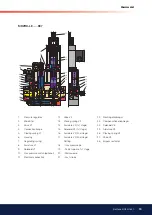
Page 15: ...g 8 Armature V1 9 Solenoid V1 10 Gas pressure switch optional 11 Electrical connection 12 Valve V2 13 Closing spring V2 14 Armature V2 1st stage 15 Solenoid V2 1st stage 16 Armature V2 2nd stage 17 Ar...

Page 16: ...via setting screw 18 The output pressure acts via opening E on the working diaphragm of the regulator In regulated state setting spring inlet pressure and pressure of working diaphragm are in force eq...

Page 17: ...ilter cup 1 2 6 5 4 5 4 2 0 0 p extern PN1 DN 4 min 5 x DN p p a p Br p a p Br Br F pL 7 8 9 3 p e 3 p e V N N V 1 0 7 6 9 8 5 3 4 1 0 7 5 3 4 2 2 2 4 Electritrical connection MB VEF 407 420 S 10 S 30...

Page 18: ...zle 9 Ionisation electrode 10 Motor 11 Connection gas ittings 12 Ignition transformer 13 Air damper 14 Air damper motor 15 Air pressure switch 16 Fuse holder 17 Indicating lamp Stage 2 Change over swi...

Page 19: ...n the screws B on both sides Loosen the stop bolt C on the pull rods Loosen the ignition cable and the ionisation cable from the gas assembly Pull out the burner on the pull rods and put it in a suita...

Page 20: ...sc in the blast tube Sometimes it is necessary to adjust the position of the shrouded disc in the blast tube This can be done with the screw E can be adjusted when the burner is in operation If you tu...

Page 21: ...21 Bentone BG550 650 General 4 3 Wiring diagram LFL1 BG550 BG650 2 Steg...

Page 22: ...22 Bentone BG550 650 General 4 4 Wiring diagram LFL1 BG550 BG650 Modulating...

Page 23: ...Gas pressure switch max S20 Main switch K1 Motor contactor with thermal overload protector R1 UV detector T1 Ignition transformer P1 Time meter total operating time P2 Time meter high capacity total o...

Page 24: ...open The gas is ignited The ionization electrode indicates a lame 5 The safety time expires The ignition spark goes out The safety time expires If there is no lame or if for some reason the lame disap...

Page 25: ...en closed between terminals 12 and 4 or 4 and 5 1 Lockout because no lame signal has been received on completion of the 1st safety time Any flame signal failure after completion of the first safety ti...

Page 26: ...water or a leak location spray After tightening repeat the test Electric function test Ensure that phase and neutral are not reversed The gas shut off cock should be closed To prevent the gas pressur...

Page 27: ...27 Bentone BG550 650 General Natural gas LGP Natural gas LPG UV sond Inner assembly Natural gas LPG Ionisation...

Page 28: ...273 t 1013 25 273 B Pu t Temperature of the gas at the gas meter 15 C B Barometer height 945 mbar Pu Pressure of the gas at the gas meter 15 0 mbar f 273 15 1013 25 273 945 15 f 11 1 The gas volume r...

Page 29: ...ng spindle B Turn clockwise Reducing outlet pressure setpoint 3 Check setpoint 4 Screw on protective cap A Replace setting spring 3 4 1 Remove protective cap A Release spring by turning adjustment spi...

Page 30: ...Outlet lange 11 Test point connection M4 down stream of valve 2 12 Gas low direction 13 Bypass throttle pilot lame adjustment 14 Vent nozzle regulator 15 Filter below cover 16 Inlet lange 17 Test poin...

Page 31: ...trical connection to screw terminals 1 2 3 6 Perform leakage and function test 7 Set switching point Remove cover B if there is no contact from terminal 1 to terminal 3 when valve is closed Rotate set...

Page 32: ...to the right the gas low is reduced to the left the gas low is increased Do not forget to tighten the lock screw again Adjustment of pressure governor Adjust outlet pressure from governor by means of...

Page 33: ...9 Setting screw ratio V high capacity 10 Test point connection G 1 8 downstream of ilter possible of both sides 11 Test point connection M4 downstream of V2 12 Setting screw zero point adjustment N l...

Page 34: ...onnection G 1 8 downstream of ilter possible on both sides 9 Test point connection G 1 8 downstream of V2 10 Setting screw zero point adjustment N 11 G 1 8 pressure connection for pF furnace pressure...

Page 35: ...IN 40050 Gas family 1 2 3 Outlet pressure 0 5 100 mbar Zero point adjustment N 2 mbar Pressure switch DIN3398 TI Fan pressure PL0 4 100 mbar Fire room pressure PF 2 5mbar Burner pressure PBr 0 5 100 m...

Page 36: ...upstream of V1 possible on both sides 7 Gas low direction 8 Outlet lange 9 Test point connection G 1 8 downstream of valve 1 possible on both sides 10 Test point connection G 1 8 possible 11 Solenoid...

Page 37: ...ows it is also necessary to adjust as above 8 12 Adjustment of start gas flow Remove the protective cover c Turn the adjustment knob d use the protective cover as a tool to the desired start gas low T...

Page 38: ...he air volume Turn orange cam towards 0 Increase the air volume Turn orange cam towards 90 Adjust the operating switch back to low load and check the air volume Full load Adjust the operating switch t...

Page 39: ...dle does not licker increase N When the lame is established adjust the gas low by means of the screw N Use a lue gas instrument Change over to max load press the switch increase Adjust the gas low wit...

Page 40: ...eady for start up Howerer study the sections dealing with adjustments of multi bloc combustion air and combustion head Open the ball valve and switch on the main switch If the burner starts the actual...

Page 41: ...r control Connect the A meter see igure Min required ionisation current according to table In practice this current must be considerably higher preferably more than 10 A All the gas burners are equipp...

Page 42: ...the gas pressure is too low and prevent the burner from starting Too low a gas pressure during operation should stop the burner The burner may start again when the rated gas pressure has been reached...

Page 43: ...leased to the control box after approx 30 s and the yellow LED lights up If the test section is leaky or if the pressure increase by 20 mbar is not attained during the test period max 26 s the VPS 504...

Page 44: ...er Motor pump Solenoid valve Differential pressure sensort Release signal Controller Motor pump Solenoid valve Differential pressure sensor Release signal Controller Motor pump Solenoid valve Solenoid...

Page 45: ...al troubles Trouble free operation is depending on three factors electricity gas and air supply Should there be any changes in the ratio between these three factors there is a risk of break downs It h...

Page 46: ...t Cause Remedy The burner does not start No gas Check that all gas cocks are open No voltage Check fuses thermostats and electrical connections The burner motor fails to start The thermal protection h...

Page 47: ...ty authorities The ignition electrodes are disturbing the ionisation current Adjust the ignition electrodes repole the ignition transformer if necessary Bad earthing Arrange for proper earthing Phase...

Page 48: ...transformern Bad combustion Bad draught conditions Check the chimney The lue gas temperature is too high The boiler is overloaded Reduce the quantity of gas The CO2 content is too low Check the boile...

Page 49: ...en inte l st ut 3 Kontrollera andra termostater ex rumstermostat om s dan inns 4 Kontrollera att tillr ckligt gastryck inns till br nnaren 5 Unders k att de elektriska s kringarna r hela 6 Kontrollera...

Page 50: ...y Measure ment Before After C A mbar mbar Small lame Large lame Measures Date Nm3 gas h Governor CO2 CO Flue gas temp Ionisa tion current Pressure Eficiency Fire room Chimney Measure ment Before After...

Page 51: ......

Page 52: ...Enertech AB P O Box 309 SE 341 26 Ljungby www bentone se www bentone com...

Reviews: