


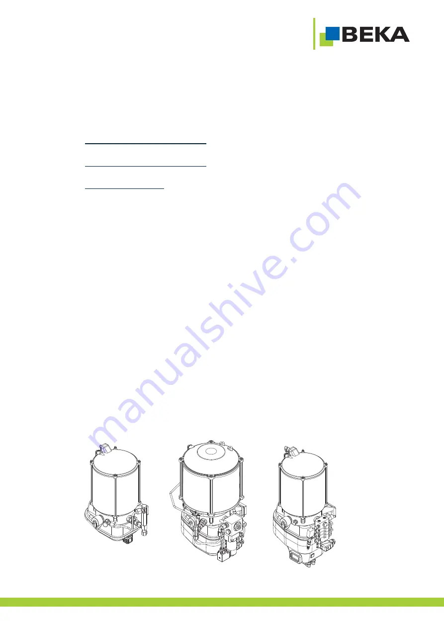
Central lubrication pump
Article-no.
2076 . ......
FKGGM-EP / EPR
V DC
FKGGM-EP / EPR
V AC
FKGGM-EP
with installed MX-F distributor
- without control unit
- with integrated control unit EP-tronic 2157. .....
- with integrated control unit BEKA-troniX1 2175. .....
- with integrated control unit EP-tronic ZX 2060. .....
- with integrated control unit EP-tronic ZX - S1 2060. .....
- with integrated control unit EP-tronic ZX - S2 2060. .....
State of art: 01 / 2019
Original operating
and
assembly instructions
1
Subject to alterations!
...a product from
BAL2076_central lubrication pump_01
19EN
© BEKA
2019 All rights reserved


