

SETTING UP THE ROUTER
Quick Install Guide
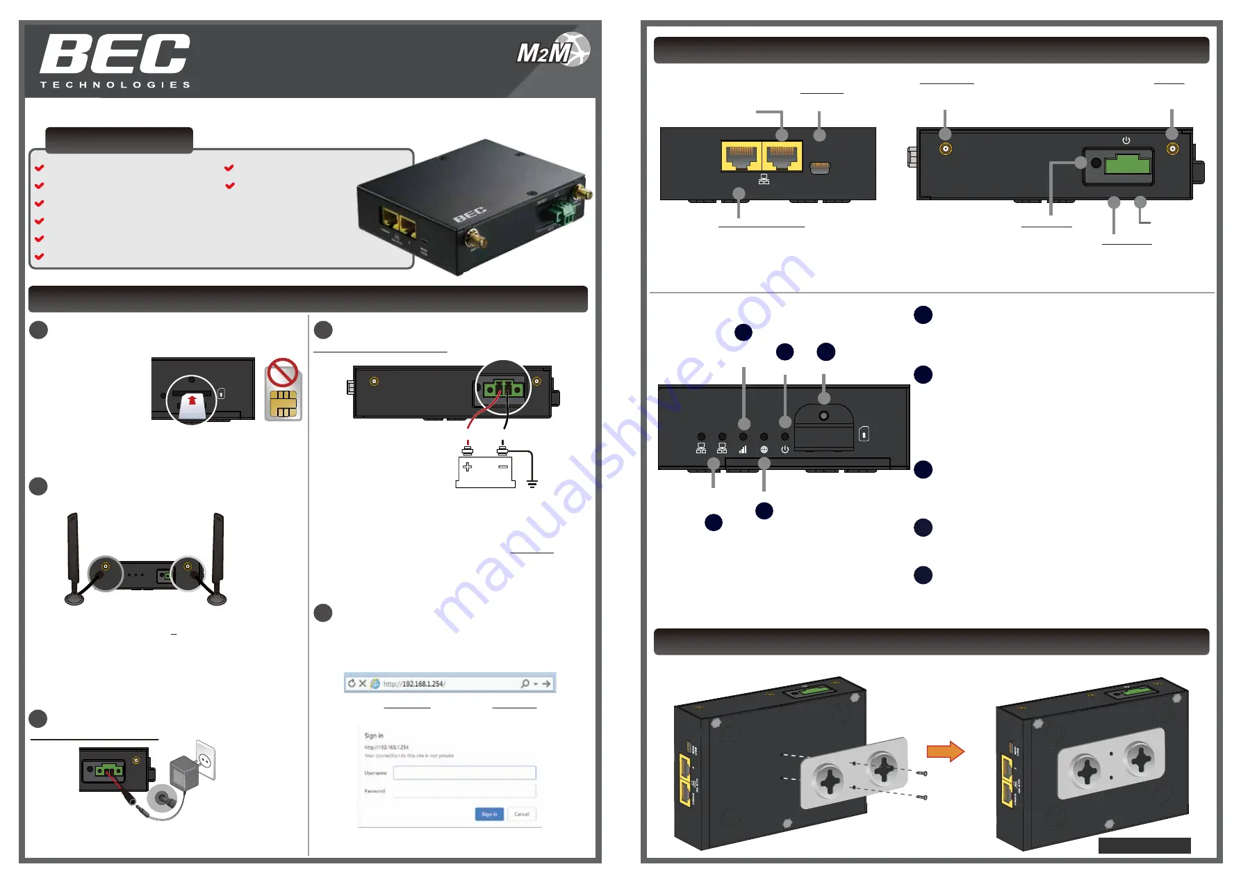
WHAT’S IN THE BOX
4 x SX-CBRS Antennas
(Sold Separately)
1 x BEC MX-240
1 x This Quick Install Guide
1 x Ethernet (RJ-45) Cable
1 x DC Power Adapter, 12V 1.2A
1 x Power Terminal Block 2-Pin 3.5mm
1 x Power Converter with 2-Pin Terminal Block
Model: MX-240
DEVICE OVERVIEW & LEDS
M
2
M
2
Attach the SX-CBRS Antennas
3
Connect to Power Source (Cont.)
1
Insert the SIM Card
POWER
INTERNET
WAN
Gb ETH
1
2
SIM
SIM
POWER
INTERNET
WAN
Gb ETH
1
2
SIM
SIM
3
Connect to Power Source
4
Access to the MX-240
C
onnect the supplied Ethernet cable to your notebook or PC.
A
cecess to the MX-240 Web interface by entering
http://192.168.1.254
in the address bar of the web browser.
Default Login
: Username (
admin
) and Password (
admin
or
a unique12-digit password can be found on the device label).
T
he
Quick Start Wizard
provides key steps to connect the
MX-240 to the Internet.
SIM
2
1
2
Ethernet
LAN
1
3
4
LTE Signal
Strength
Internet
Power SIM Slot
INTERNET
Green: IP traffic via WAN
Red: WAN IP request failed
Off: No WAN Connection or in Bridge Mode
3
2
WAN (Cellular Signal Strength Indicator)
Green: RSSI > -69 dBm. Excellent signal
Green / Fast Flashing: -69 > RSSI > -81dBm. Good signal
Red / Fast Flashing: -81 > RSSI > -99dBm. Fair signal
Red / Slow Flashing: -99dBm > RSSI. Poor signal
Red: No signal and the 4G LTE module is in service
Off: No LTE module or LTE failure
1
GIGABIT ETHERNET (Gb ETH) (LAN #1 & #2)
Green: Transmission speed is at Gigabit speed (1000Mbps)
Orange: Transmission speed is at 10/100Mbps
Blinking: Data being transmitted/received
POWER
4
Green: System ready
Red: Boot failure
5
SIM Card Slot
5
Insert mini SIM card (2FF) with the gold contact facing down.
Push mini SIM card (2FF) inwards to eject it
* Power off the MXConnect router before inserting or removing the SIM card
Note: Power off the MX-240 before inserting or removing the SIM
R
emove the SIM cover
then insert the SIM card
(2FF) with the mental
contacts (gold plate)
facing down to the SIM
slot then push it all the
way in until you hear the clicking sound.
R
eplace the metal SIM cover after inserting the SIM.
VCC(on the left) - Red Wire
GND(on the right) - Black Wire
POWER
RESET
ANT 1
ANT 0
(MAIN)
POWER
RESET
GND
VCC
Use External Power Supply
A
ttach the
power terminal block (TB)
to the MX-240 and
connect wire leads from a power supply to the terminal block
(TB) plug.
R
ED Wire (Left Connector): VCC/V+. Connect to the positive
supply voltage.
I
nput voltage range is from 9V to 56V.
B
LACK Wire (Right Connector): Ground (GND) / V-. Connect
to the negative supply voltage.
WALL MOUNT KIT INSTALLATION
A
ttach and fasten the wall bracket to the back of the MX-240 using two (2) clip mounting screws included in the mounting
kit.
S
crew the male SMA SX-CBRS antennas tight to the female
connectors. You can use up to 4 antennas with the MX-240.
C
onnect to the ANT1(MAIN) port, the primary antenna port to
transmit and receive cellular signal, if decide to use a single
antenna.
D
o not over-torque the antenna on the connector.
POWER
RESET
WAN
AUX
WAN
MAIN
POWER
RESET
ANT 1
WAN
MAIN
POWER
RESET
WAN
AUX
ANT 0
(MAIN)
GPS
Note: Antenna images shown are for illustration purpose only.
Power
POWER
RESET
WAN
AUX
ANT 0
(MAIN)
GPS
Use the DC Power Adapter
A
ttach the power converter with 2-pin terminal block to the
MX-240 and plug in the supplied power adapter, 12VDC
1.2A.
ANT 1
ANT 0
(MAIN)
RESET
VCC
GND
MINI
USB
1/WAN
2
Gb ETH
Hard Reset
Hold for 6 seconds to
restore its factory settings
Power (V+)
1. Use an external power supply
Input power 9-56V DC range.
2. Use supplied Power adapter
Gigabit LAN
Gigabit LAN / WAN
MINI USB
Connect to the Module
ANT 1 / 2 / 3
(Auxiliary Antenna)
SMA Female Connector
ANT 0
(Main Antenna)
SMA Female Connector
Ground (V-)
Ethernet LAN: Connect to an Ethernet device.
Ethernet WAN: Software configurable in the GUI.
Connect to a broadband connection device such as
ADSL / VDSL / Cable / FTTH modem.
1 x DIN Rail Mounting Kit
1 x Wall Mounting Kit
ANT 1
ANT 0
(MAIN)
GPS
RESET
VCC
GND
ANT 1
ANT 0
(MAIN)
GPS
RESET
VCC
GND
Assembled


