background image

INSTRUCTION MANUAL 

FOR 

OVERCURRENT RELAYS 

BE1-50/51B-219 and BE1-50/51B-226 


 Publication: 

9252000981 

 Revision: 

03/08 


Содержание BE1-50/51B-219

Страница 1: ...INSTRUCTION MANUAL FOR OVERCURRENT RELAYS BE1 50 51B 219 and BE1 50 51B 226 Publication 9252000981 Revision G 03 08...

Страница 2: ......

Страница 3: ...Controls and Indicators Functional Description Installation and Maintenance Testing WARNING To avoid personal injury or equipment damage only qualified personnel should perform the procedures in this...

Страница 4: ...peration The availability and design of all features and options are subject to modification without notice Should further information be required contact Basler Electric BASLER ELECTRIC ROUTE 143 BOX...

Страница 5: ...on 4 Installation D 12 00 Updated drawings in Section 2 to reflect changes to the PC board Updated drawings to reflect changes to the overlay Also updated the rest of the manual to reflect the change...

Страница 6: ...iv BE1 50 51B 219 226 Introduction 9252000981 Rev G This page intentionally left blank...

Страница 7: ...9 226 Introduction v CONTENTS SECTION 1 GENERAL INFORMATION 1 1 SECTION 2 CONTROLS AND INDICATORS 2 1 SECTION 3 FUNCTIONAL DESCRIPTION 3 1 SECTION 4 INSTALLATION 4 1 SECTION 5 TESTING 5 1 APPENDIX A T...

Страница 8: ...vi BE1 50 51B 219 226 Introduction 9252000981 Rev G This page intentionally left blank...

Страница 9: ...nsient Response 1 7 Harmonic Response 1 7 Target Indicators 1 8 Output Contacts 1 8 Type Tests 1 8 Environment 1 9 Agency Recognition 1 9 Physical 1 9 Figures Figure 1 1 Integrating Reset Characterist...

Страница 10: ...ii BE1 50 51B 219 226 General Information 9252000981 Rev G This page intentionally left blank...

Страница 11: ...antaneous and time overcurrent protection for 50 Hz or 60 Hz power systems Each model covers 15 popular time characteristics a wide range of pickup settings and field selectable instantaneous or integ...

Страница 12: ...tions are listed in the following paragraphs Current Sensing Input BE1 50 51B 219 Continuous Current 14 Aac One Second Rating 400 Aac BE1 50 51B 226 Continuous Current 2 8 Aac One Second Rating 80 Aac...

Страница 13: ...listed in Tables 1 2 and 1 3 Constants have been selected to conform to the characteristics of electromechanical relays over a range of pickup multiples from 1 3 to 40 Values of the constants are prov...

Страница 14: ...rt Inverse V Very Inverse L Long Inverse E Extremely Inverse D Definite Time B BS142 Very Inverse M Moderately Inverse C BS142 Extremely Inverse I Inverse F Fixed Time Delay Figure numbers refer to th...

Страница 15: ...cal instantaneous units However the time to trip for applications where the initial current through the relay is less than 0 4 ampere 5 ampere relay or 0 08 ampere 1 ampere relay may be slightly longe...

Страница 16: ...ion 9252000981 Rev G Figure 1 2 Instantaneous Characteristic Curves Burden Burden is non linear Figure 1 3 illustrates the device burden BE1 50 51B 219 At 0 5 amperes 4 8 At 5 0 amperes 0 2 BE1 50 51B...

Страница 17: ...uses 0 5 change in the current required for pickup Transient Response 10 overreach with system time constants up to 40 ms Harmonic Response Figure 1 4 shows that a relay set for 1 ampere pickup would...

Страница 18: ...or 2 minutes 3 amperes continuously and break 5 amperes 125 250 Vdc Make 30 amperes for 0 2 seconds carry 7 amperes for 2 minutes 3 amperes continuously and break 0 3 ampere Inductive Ratings 120 240...

Страница 19: ...of three mutually perpendicular planes swept over the range of 10 to 500 Hz for a total of 6 sweeps 15 minutes each sweep Shock Withstands 15 G in each of three mutually perpendicular planes Environm...

Страница 20: ...1 10 BE1 50 51B 219 226 General Information 9252000981 Rev G This page intentionally left blank...

Страница 21: ...2 CONTROLS AND INDICATORS TABLE OF CONTENTS SECTION 2 CONTROLS AND INDICATORS 2 1 INTRODUCTION 2 1 Figures Figure 2 1 Front Panel Controls and Indicators 2 1 Figure 2 2 Location of SW3 2 2 Tables Tab...

Страница 22: ...ii BE1 50 51B 219 226 Controls and Indicators 9252000981 Rev G This page intentionally left blank...

Страница 23: ...es the front panel controls and indicators of the BE1 50 51B 219 and BE1 50 51B 226 Figure 2 2 illustrates the location of switch SW3 Both illustrations have lettered call outs that correspond to the...

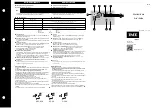
Страница 24: ...2 2 BE1 50 51B 219 226 Controls and Indicators 9252000981 Rev G P0053 50 SW3 Figure 2 2 Location of SW3...

Страница 25: ...anical relay at its maximum dial setting G TIME MANUAL TRIP Test Points When shorted the test points provide a secure means to manually trip the controlled breaker Jacks accept a standard 0 08 inch di...

Страница 26: ...2 4 BE1 50 51B 219 226 Controls and Indicators 9252000981 Rev G This page intentionally left blank...

Страница 27: ...DESCRIPTION TABLE OF CONTENTS SECTION 3 FUNCTIONAL DESCRIPTION 3 1 GENERAL 3 1 FUNCTIONAL DESCRIPTION 3 1 Sensing Input 3 1 Power Supply 3 1 Instantaneous Signal 3 1 Time Signal 3 1 Microprocessor 3 1...

Страница 28: ...ii BE1 50 51B 219 226 Functional Description 9252000981 Rev G This page intentionally left blank...

Страница 29: ...roprocessor supervisor circuit When the microprocessor is active and executing code the ACTIVE PICKUP LED is green When the input current falls below an acceptable level the supervisor circuit interru...

Страница 30: ...the TIME or INST MANUAL TRIP front panel test points Current flow in the trip circuit is indicated by the operation of the target The targets will not operate without adequate operating power for the...

Страница 31: ...CONTENTS SECTION 4 INSTALLATION 4 1 GENERAL 4 1 FACTORY SETTINGS 4 1 INSTALLATION 4 1 APPLICATION COORDINATION 4 1 CONNECTIONS 4 3 MAINTENANCE 4 4 STORAGE 4 4 Figures Figure 4 1 Coordination Timing Di...

Страница 32: ...ii BE1 50 51B 219 226 Installation 9252000981 Rev G This page intentionally left blank...

Страница 33: ...e BE1 50 51B 219 or BE1 50 51B 226 relay Select the desired relay settings on your new BE1 50 51B 219 226 relay Remove the existing ABB relay cradle Insert the new relay cradle and close the cradle la...

Страница 34: ...0 1 10 2 7624 7 0938 2 028 0 05516 0 1 10806 124 5248 15 seconds 0 29 From the reset characteristic curve equation 1 M RD T 2 Reset seconds 15 5 1 0 2 7 75 2 M 0 if current goes to zero Negative resul...

Страница 35: ...ewind Trip Full T Occurence This Trip Second Operation 15 5 3 0 209 TB seconds 0 040 TB Third Operation 15 5 11 96 0 209 TC seconds 0 161 TC CONNECTIONS Typical ac input and dc control connections are...

Страница 36: ...ic checks should be performed according to scheduled practices A recommended periodic test is provided in Section 5 If the relay fails to function properly contact the Technical Sales Support Departme...

Страница 37: ...TEST PROCEDURE 5 1 Test Equipment Required 5 1 Test Procedure Models BE1 50 51B 218 Five Ampere Sensing Input 5 3 Test Procedure Models BE1 50 51B 228 One Ampere Sensing Input 5 5 SETTING THE RELAY 5...

Страница 38: ...ii BE1 50 51B 219 226 Testing 9252000981 Rev G This page intentionally left blank...

Страница 39: ...eration of relays BE1 50 51B 219 5 ampere model and BE1 50 51B 226 1 ampere model The test setup of Figures 5 1 and 5 2 are intended primarily as an illustration of the principles involved Other test...

Страница 40: ...0981 Rev G Figure 5 1 Pickup and Timing Test Setup 1 0 Aac CURRENT LIMITER TARGET CURRENT BE1 50 51B 219 8 9 1 2 TIME INST 10 CURRENT SOURCE INPUT STOP TIMER START AMPS TEST SET 12 13 99 D2354 20 Figu...

Страница 41: ...tup as shown in Figure 5 1 Insure that SW3 switches are set SW3 1 for the operating frequency SW3 2 to OFF SW3 3 to ON and SW3 4 ON Set TIME DIAL to 0 0 Set CURVE to S Set TIME PICKUP to 1 0 Set INST...

Страница 42: ...current and reset targets Manual Trip Test Perform preliminary setup Connect test setup as shown in Figure 5 2 Insure that SW3 switches are set SW3 1 for the operating frequency SW3 2 to OFF SW3 3 to...

Страница 43: ...Step 3 Set TIME PICKUP to 0 44 Step 4 Slowly increase current to terminals 8 and 9 PICKUP LED should change from GREEN to RED at an input current of 0 426 to 0 454 amperes Step 5 Decrease input curre...

Страница 44: ...rent and reset targets Manual Trip Test Perform preliminary setup Connect test setup as shown in Figure 5 2 Insure that SW3 switches are set SW3 1 for the operating frequency SW3 2 to OFF SW3 3 to ON...

Страница 45: ...hdrawn one at a time for testing purposes without losing protection Only three are required at any one time to sense all types of faults on a grounded wye system Refer to Figures 5 1 and 5 2 for recom...

Страница 46: ...5 8 BE1 50 51B 219 226 Testing 9252000981 Rev G This page intentionally left blank...

Страница 47: ...Similar to ABB CO 8 A 5 Figure A 6 Time Characteristic Curve V Very Inverse SW3 3 OFF Similar to ABB CO 9 A 6 Figure A 7 Time Characteristic Curve E Extremely Inverse SW3 3 OFF Similar to ABB CO 11 A...

Страница 48: ...ii BE1 50 51B 219 226 Time Characteristic Curves 9252000981 Rev G This page intentionally left blank...

Страница 49: ...DIX A TIME CHARACTERISTIC CURVES TIME CHARACTERISTIC CURVES Figures A 1 through A 14 illustrate the time characteristic curves that are programmed into the nonvolatile memory of this relay Figure A 1...

Страница 50: ...A 2 BE1 50 51B 219 226 Time Characteristic Curves 9252000981 Rev G Figure A 2 Time Characteristic Curve L Long Inverse SW3 3 OFF Similar to ABB CO 5...

Страница 51: ...9252000981 Rev G BE1 50 51B 219 226 Time Characteristic Curves A 3 Figure A 3 Time Characteristic Curve D Definite Time Similar to ABB CO 6...

Страница 52: ...A 4 BE1 50 51B 219 226 Time Characteristic Curves 9252000981 Rev G Figure A 4 Time Characteristic Curve M Moderately Inverse Similar to ABB CO 7...

Страница 53: ...9252000981 Rev G BE1 50 51B 219 226 Time Characteristic Curves A 5 Figure A 5 Time Characteristic Curve I Inverse SW3 3 OFF Similar to ABB CO 8...

Страница 54: ...A 6 BE1 50 51B 219 226 Time Characteristic Curves 9252000981 Rev G Figure A 6 Time Characteristic Curve V Very Inverse SW3 3 OFF Similar to ABB CO 9...

Страница 55: ...9252000981 Rev G BE1 50 51B 219 226 Time Characteristic Curves A 7 Figure A 7 Time Characteristic Curve E Extremely Inverse SW3 3 OFF Similar to ABB CO 11...

Страница 56: ...A 8 BE1 50 51B 219 226 Time Characteristic Curves 9252000981 Rev G Figure A 8 Time Characteristic Curve BS142 B BS142 Very Inverse...

Страница 57: ...9252000981 Rev G BE1 50 51B 219 226 Time Characteristic Curves A 9 Figure A 9 Time Characteristic Curve BS142 C BS142 Extremely Inverse...

Страница 58: ...A 10 BE1 50 51B 219 226 Time Characteristic Curves 9252000981 Rev G Figure A 10 Time Characteristic Curve S2 Short Inverse SW3 3 ON Similar to GE IAC 55...

Страница 59: ...9252000981 Rev G BE1 50 51B 219 226 Time Characteristic Curves A 11 Figure A 11 Time Characteristic Curve L2 Long Inverse SW3 3 ON Similar to GE IAC 66...

Страница 60: ...A 12 BE1 50 51B 219 226 Time Characteristic Curves 9252000981 Rev G Figure A 12 Time Characteristic Curve I2 Inverse SW3 3 ON Similar to GE IAC 51...

Страница 61: ...9252000981 Rev G BE1 50 51B 219 226 Time Characteristic Curves A 13 Figure A 13 Time Characteristic Curve V2 Very Inverse SW3 3 ON Similar to GE IAC 53...

Страница 62: ...A 14 BE1 50 51B 219 226 Time Characteristic Curves 9252000981 Rev G Figure A 14 Time Characteristic Curve E2 Extremely Inverse SW3 3 ON Similar to GE IAC 77...

Страница 63: ...ROUTE 143 BOX 269 HIGHLAND IL 62249 USA http www basler com info basler com PHONE 1 618 654 2341 FAX 1 618 654 2351...

Отзывы: