ABB CR Series, Instruction Leaflet
The ABB CR Series Instruction Leaflets are comprehensive manuals designed to guide users through the functionalities and set-up procedures of the product. Available for free download at manualshive.com, these user-friendly manuals offer detailed step-by-step instructions and expert tips to optimize your experience with the ABB CR Series.
Share
Download


Reviews:
No comments
Related manuals for CR Series

VLT VLA 31
Brand: Danfoss Pages: 4
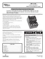
White Rogers SureSwitch 49P11-843
Brand: Emerson Pages: 12

Liebert IntelliSlot IS-RELAY
Brand: Emerson Pages: 8

Alco Controls PS4 Series
Brand: Emerson Pages: 2

UPS2MB01
Brand: COQON Pages: 2

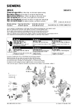
SIRIUS SRF2 Series
Brand: Siemens Pages: 3

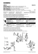
SRC-8
Brand: Siemens Pages: 4

SIRIUS 3ZX1012-0RU11-1DA1
Brand: Siemens Pages: 4

SIRIUS S00
Brand: Siemens Pages: 7

SIRIUS 3UG4851 Series
Brand: Siemens Pages: 6

SIRIUS 3UG4841
Brand: Siemens Pages: 8
SIRIUS 3UG4513
Brand: Siemens Pages: 4

SIRIUS 3UG4501
Brand: Siemens Pages: 4

Sirius 3UG4651
Brand: Siemens Pages: 8
Sirius 3UG4614
Brand: Siemens Pages: 6

SIRIUS 3UG4631
Brand: Siemens Pages: 8

SIRIUS 3UG4624
Brand: Siemens Pages: 7

SIRIUS 3UG4641-1 Series
Brand: Siemens Pages: 8


