background image

Quick Start Guide

Self-contained Smart Camera with User-Friendly Vision Manager Software

This guide is designed to help you set up and install the VE Series Smart Camera. For complete information on programming, performance,

troubleshooting, dimensions, and accessories, please refer to the Instruction Manual at 

www.bannerengineering.com

. Search for p/n 191666 to view

the Instruction Manual. Use of this document assumes familiarity with pertinent industry standards and practices. More details are available in the

online help.

WARNING: Not To Be Used for Personnel Protection

Never use this device as a sensing device for personnel protection. Doing so could lead to serious injury or death. This device

does not include the self-checking redundant circuitry necessary to allow its use in personnel safety applications. A sensor

failure or malfunction can cause either an energized or de-energized sensor output condition.

CAUTION: Electrostatic Discharge

Avoid the damage that electrostatic discharge (ESD) can cause to the Sensor.
Always use a proven method for preventing electrostatic discharge when installing a lens or attaching a cable.

CAUTION: Hot Surface

Use caution when handling the camera. The surface of the camera may be hot during operation and immediately after use.

Models

Model 1

Resolution

Type

VE200G1A

WVGA, 752 × 480 pixels grayscale

Vision

VE201G1A

1.3 MP, 1280 × 1024 pixels grayscale

Vision

VE202G1A

2 MP, 1600 × 1200 pixels grayscale

Vision

VE205G1A

5 MP, 2592 × 2048 pixels grayscale

Vision

VE200G1B

WVGA, 752 × 480 pixels grayscale

ID

VE201G1B

1.3 MP, 1280 × 1024 pixels grayscale

ID

VE202G1B

2 MP, 1600 × 1200 pixels grayscale

ID

VE205G1B

5 MP, 2592 × 2048 pixels grayscale

ID

VE200G1C

WVGA, 752 × 480 pixels grayscale

ID

VE201G1C

1.3 MP, 1280 × 1024 pixels grayscale

ID

VE202G1C

2 MP, 1600 × 1200 pixels grayscale

ID

VE205G1C

5 MP, 2592 × 2048 pixels grayscale

ID

Features

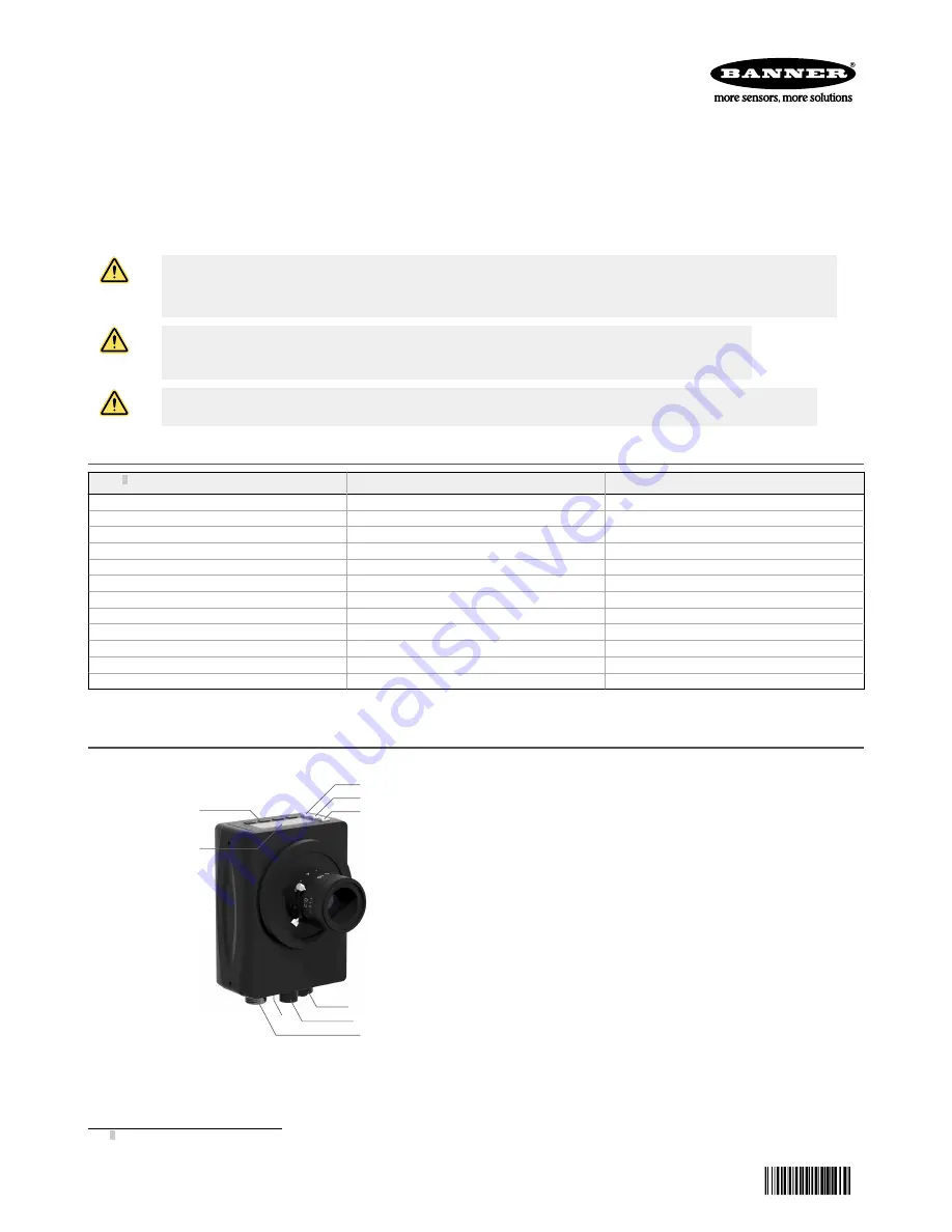
Figure 1. Sensor Features

1

2

3

4

5

7

6

8

9

1. Display

2. Buttons

3. Pass/Fail indicator (green/red)

4. Ready/Trigger indicator (green/amber)

5. Power/Error indicator (green/red)

6. Ethernet indicator (amber), not shown

7. Ethernet connection

8. Light connection

9. Power, Discrete I/O connection

1 Model VE202G2A, 2 MP, 1600 × 1200 grayscale with 4-pin D-code M12 Ethernet connection is also available.

VE Series Smart Camera


Original Document

191667 Rev. J

17 March 2021

191667

Summary of Contents for VE200G1B

Page 1: ...rostatic discharge when installing a lens or attaching a cable CAUTION Hot Surface Use caution when handling the camera The surface of the camera may be hot during operation and immediately after use...

Page 2: ...e Vision Manager to configure Banner vision devices including iVu Vision Sensors and VE Smart Cameras Installation Instructions Install the Accessories Figure 3 Install the Accessories 1 2 3 5 4 1 VE...

Page 3: ...screte I O connections 3 Connect the external light cable optional to the light connection 2 if the light is powered by the sensor CAUTION Use Appropriate Power If the light is powered by the sensor t...

Page 4: ...ystem settings a popup window may appear prompting to allow Vision Manager to make changes to your computer Click Yes 7 Click Close to exit the installer Getting Started Power up the sensor and verify...

Page 5: ...Summary the I O Summary and the Test Summary 5 Parameters pane Includes user adjustable Inputs parameters or Test parameters for the tools in an inspection depending on what is selected in the Tools a...

Page 6: ...ick Add New Inspection A new inspection is added to the list the Image pane updates and the Tools Results tab shows only the camera tool 3 Add tools and adjust them as needed for the inspection Add a...

Page 7: ...able to go back to previous settings Use the following procedure to save a copy of an inspection to your computer or a network location 1 On the Inspection Management screen click Transfer 2 Change th...

Page 8: ...s When navigating the menu systems the menu items loop Enter Button Press Enter to Access the Sensor Menu Access the submenus Save changes In the Sensor Menu a check mark in the lower right corner of...

Page 9: ...Home Screen SPEED LINK SUBNET GATEWAY STATUS IP PSELECT TRIGGER INPUT MAC MAX SPD By NUM OUTPUT FW VER BOOT NAME MODEL HOUR SERIAL SLEEP VIEW Ethernet Menu Product Change by Slot No Bit Representation...

Page 10: ...ose title merchantability data loss non interference with or non infringement of any intellectual property rights or the accuracy reliability quality or content in or linked to the services Banner and...

Page 11: ...CONSEQUENTIAL OR SPECIAL DAMAGES RESULTING FROM ANY PRODUCT DEFECT OR FROM THE USE OR INABILITY TO USE THE PRODUCT WHETHER ARISING IN CONTRACT OR WARRANTY STATUTE TORT STRICT LIABILITY NEGLIGENCE OR O...

Reviews: