


M-Series® M5000
Firmware Upgrade
MAG-UM-00945-EN-02 (August 2014)
Installation Manual
PREPARING FOR THE FIRMWARE UPGRADE
Meters that currently have version 1.x firmware can be upgraded
only to the latest 1.x firmware. Meters that currently have version
2.x firmware can be upgraded to the latest 2.x firmware. If you have
1.x firmware and wish to upgrade to 2.x firmware, you will need to
upgrade the board.
Download the latest firmware version from our website at
www.badgermeter.com
to your hard drive. With the
Flow Meter Tool
software installed, connect the laptop to the meter using either the
supplied RS232 cable or an IrDA adapter.
OTEE:
N
The M5000 Data Logging kit (p/n 67354-008) is needed to
perform the firmware upgrade. See the
M5000 Data
Logging Installation Manual.
RS232 Connection
1. Identify / Configure the meter’s communication settings:
a. Navigate to
Communications > Interface
.
b. Set the interface to
SERIAL
.
OTEE:
N
The interface must be set to
SERIAL
. All other settings
can be set as desired by the operator and must match
those settings of the software tool.
c. Record or change other interface parameters (parity
and baud rate).
2. Connect the supplied RS232 cable into the RS232 connector of
the meter. Either connect the serial connector to a COM port or
connect it to the USB adapter.
3. Open the Flow Meter Tool installed on the laptop or PC. Go to
Start > All Programs > Badger Meter
to open the flow meter tool
application.
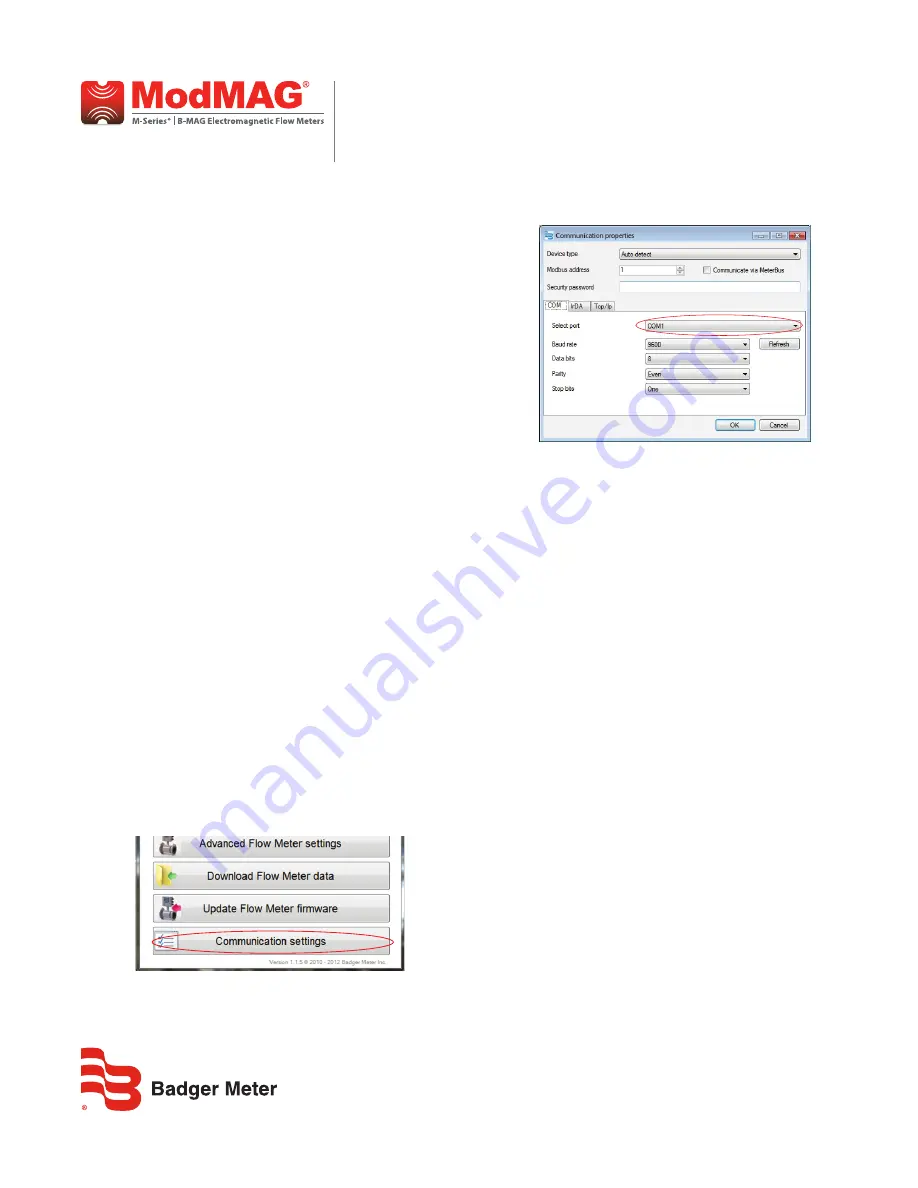
4. To configure the flow meter tool software communication
settings:
a. Select
Communication Settings
.
b. Change the following parameters as necessary to
align with the meter settings:
•
MODBUS ADDRESS (Node Address)
•
BAUD RATE (9600)
•
DATA BITS (default is 8)
•
PARITY
•
STOP BITS (default is 1)
c. Select
OK
to confirm the configuration of the
communication port. Make sure you select the
correct COM port.
OTEE:
N
The M5000 communicates via the COM port and IrDA.
TCP/IP is not supported.
IrDA Connection
1. Identify / Configure the meter’s communication settings:
a. Navigate to
Communications > Interface.
b. Set the interface to
IrDA
.
OTEE:
N
The interface must be set to
IrDA
. All other settings can
be set as desired by the operator and must match those
settings of the software tool.
3. On the M5000 enclosure, install the IrDA bracket. Then install
the IrDA cable.
4. Connect the IrDA cable from the M5000 to the laptop.
5. If necessary, install the rDA link drivers from the CD. The IrDA
link uses a USB/IrDA converter and drivers. You may have to
restart your computer after installing the drivers.


