Audio Technica SmartMixer AT-MX351, Installation And Operation Manual
The Audio Technica SmartMixer AT-MX351 is a high-quality audio mixing device designed for professional installations. This versatile product ensures seamless integration and smooth operation of various audio sources. For detailed instructions on its installation and usage, you can easily download the free "Installation And Operating Manual" from manualshive.com.
Share
Download


Reviews:
No comments
Related manuals for SmartMixer AT-MX351
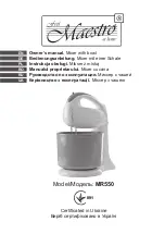
MR550
Brand: Maestro Pages: 52

GM Series
Brand: Faggiolati Pumps Pages: 38

delish DCSM350
Brand: Dash Pages: 25

SMA-12800U
Brand: FONESTAR Pages: 12

EPSILON II
Brand: KAHAYAN Proaudio Pages: 13

L2 PLUS
Brand: Feelworld Pages: 35

MC32/12
Brand: Yamaha Audio Pages: 18

LAN Console
Brand: Fujitsu Pages: 139

5KSM7586P
Brand: KitchenAid Pages: 32
9KSM180 Series
Brand: KitchenAid Pages: 32

KEC97A
Brand: KitchenAid Pages: 32

5KSM65 Series
Brand: KitchenAid Pages: 12

Artisan Series
Brand: KitchenAid Pages: 61

CommerCial mixer
Brand: KitchenAid Pages: 48
5KSM175PSRBK0
Brand: KitchenAid Pages: 21

5KSM1CBL
Brand: KitchenAid Pages: 15
KEA26 Series
Brand: KitchenAid Pages: 40

KF26M22CA
Brand: KitchenAid Pages: 40


