AT&T Digital Life, Инструкция по установке и эксплуатации
AT&T Digital Life - продукт для безопасности и управления умным домом. Установите и используйте его, следуя инструкциям по установке и эксплуатации. Скачать бесплатно руководство по установке и эксплуатации можно на {веб-сайте}.
Поделиться
Скачать


Отзывы:
Нет отзывов
Похожие инструкции для Digital Life
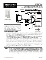
HomePro ZDW103
Бренд: Advanced Control Страницы: 7

00223582
Бренд: Hama Страницы: 38

Molekule Air Mini
Бренд: MO Страницы: 24

CT-HAEO1017-ID
Бренд: HIOTH TECHNOLOGY Страницы: 3

IQ PANEL 2
Бренд: QOLSYS Страницы: 57

00176597
Бренд: Hama Страницы: 56

U-Smart WiFi Plug Mini
Бренд: UMAX Technologies Страницы: 12

R7053
Бренд: WOOX Страницы: 32

SunRise 1-PH
Бренд: RedEarth Страницы: 25

mPERS
Бренд: Essence Страницы: 8

Care@Home Pro
Бренд: Essence Страницы: 34

WeR@Home
Бренд: Essence Страницы: 37

WeR@Home S5
Бренд: Essence Страницы: 40

WeR@Home WeR+
Бренд: Essence Страницы: 60

ASPPD6-0122
Бренд: Bauhn Страницы: 2

SL495
Бренд: Bea-fon Страницы: 66

VISITOR 1V
Бренд: Bea-fon Страницы: 73


