


This manual is a user guide for ARP-3800AP-E01 Series Fanless Touch Panel Computer. ARP-
3800AP-E01 Series of touch panel computers are industrial level all in one computers, delivering high
performance while working on low consumption.
Please read carefully the information below to get familiarity with safety installation techniques and
precautions. For any questions or support, please call us at 1.877.827.4782 Monday through Friday
8:00am to 5:00PM Pacific Time.
Publication date: 2016/09/22
Version No.: V2.1
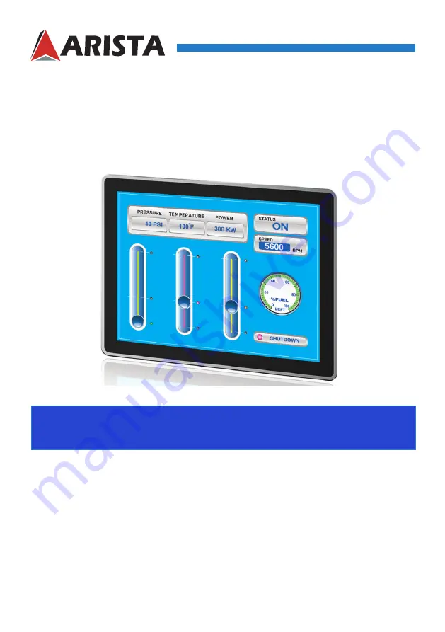
USER MANUAL
Talk to us. We listen.
ARP-3800AP-E01 Series Fanless Touch Panel Computer
ARP-3815AP-E01 ARP-3817AP-E01 ARP-3819AP-E01
ARP-3821AP-E01 ARP-3824AP-E01


