AMT Quantum7, Owner'S Manual
The Nuqleo Quantum7 is an exceptional device that combines advanced features and sleek design. Unlock its full potential by accessing the comprehensive User Manual, available for free download on our website. Discover endless possibilities and enhance your mobile experience with the Nuqleo Quantum7.
Share
Download


Reviews:
No comments
Related manuals for Quantum7

AccuSync 120
Brand: NEC Pages: 12

BeoSound 4
Brand: Bang & Olufsen Pages: 6

BeoSound 5 Encore
Brand: Bang & Olufsen Pages: 25

BeoCenter 2
Brand: Bang & Olufsen Pages: 28

FINISH-OUT MC111M
Brand: M&S Systems Pages: 2

digital slim -1400
Brand: Fisher Pages: 20

AC-CAVWC
Brand: Lightspeed Pages: 31

DQM Series
Brand: W Audio Pages: 8

Beta 91
Brand: Shure Pages: 24

HIF-4800RC
Brand: Roadstar Pages: 21

BOC-2132
Brand: Steren Pages: 26

NW-8000-USB
Brand: NEEWER Pages: 26

HIFI200
Brand: Oakcastle Pages: 25

RS2202
Brand: RCA Pages: 68

EMMC35881
Brand: Emerson Pages: 14

CA-UXP400
Brand: JVC Pages: 32

CA-V508T
Brand: JVC Pages: 48
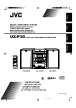
CA-UXP30
Brand: JVC Pages: 34


