manualshive.com logo in svg
background image

Installation Instr

uctions

In

s

ta

ll

a

ti

o

n

 I

n

s

tr

u

c

ti

o

n

s

(In Toronto Area only: 1-905-3061093)

SELECTRONIC™

Proximity Infection

Control Faucet

Certified to comply with ASME A112.18.1M

© 2011 American Standard

To learn more about American Standard Faucets visit our website at: 

www.us.amstd.com 

or U.S.

customer's e-mail us at: 

[email protected]

For Parts, Service, Warranty or other Assistance, 
please call


(855) 752-9259 (In Canada: 1-800-387-0369)

NOTE TO INSTALLER: Please give this manual to the customer after installation.

(In Toronto Area only: 1-905-3061093)

M 9 6 5 119   R E V.  1. 3  

Product No.'s & Options

Specifications

How to Install

Electrical Hook-up

Maintenance

FAQ,s

Replacement Parts

1

2

2-3

4-6

7-8

9

10

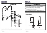
6055 / 6056 / 6057 Infection Control Faucet shown Installed on

American Standard 9118.111 Infection Control Sink

6055.193
6056.193
6057 

MODEL NUMBERS

.193

CAUTION:

  Use only American Standard 

supplied cable sets. Using non-AS supplied 
cables, or cutting, splicing or modifying any 
components will void the warranty.

Содержание SELECTRONIC 6055.193

Страница 1: ...Assistance please call 855 752 9259 In Canada 1 800 387 0369 NOTE TO INSTALLER Please give this manual to the customer after installation In Toronto Area only 1 905 3061093 M965119 REV 1 3 Product No s Options Specifications How to Install Electrical Hook up Maintenance FAQ s Replacement Parts 1 2 2 3 4 6 7 8 9 10 6055 6056 6057 Infection Control Faucet shown Installed on American Standard 9118 11...

Страница 2: ...s 1 2 12 10 11 7 8 9 4 3 Deck Plate Mixing Valve B a s e P r o d u c t 5 GN Spout M965119 REV 1 3 6055 193 6056 193 6057 193 I n s t a l l a t i o n I n s t ru c t i o n s I n s t a l l a t i o n I n s t ru c t i o n s In Toronto Area only 1 905 3061093 SELECTRONIC Proximity Infection Control Faucet Certified to comply with ASME A112 18 1M 2011 American Standard To learn more about American Standa...

Страница 3: ...nent power In line strainer for solenoid is integral Single inlet 3 8 compression built in checks and flexible stainless steel 16 1 4 reach inlet hose for spout connection 1 Connect the two 27 EXTENSION CABLES 1 to the Faucet Sensor Cables Fig 1 2 Insert 27 EXTENSION CABLES 1 FLEX HOSE 2 and SPOUT SHANK 3 through center hole of mounting surface Fig 1 3 Assemble C WASHER 4 STAR WASHER 5 and LOCKNUT...

Страница 4: ...ting surface NOTE The illustration shows the Infection Control FAUCET mounted on the American Standard Infection Control Sink Faucet can be installed on almost any sink or countertop For Faucet installation on the American Standard Infection Control Sink see instruction sheet No 7301793 100 Infection Control Sink System supplied with Sink for more detailed information NOTE For AC installation see ...

Страница 5: ...ONNECTOR 5a through GROMMET 6 as shown Fig 1c 5 Connect SOLENOID CABLE 7 and BATTERY CONNECTOR 5a to EXTENSION CABLES 2 from Faucet Sensor Fig 1d 6 Replace ENCLOSURE COVER 1 Tighten cover screws firmly DC VERSION BATTERY Fig 1 1 ELECTRICAL INSTALLATION Fig 1a Fig 1b Fig 1 Fig 1c 5a 7 2 Fig 1d 2 3 1 4 5 INSTALL BATTERY CR P2 5a 5a 6 5 CAUTION Use only American Standard supplied cable sets Using non...

Страница 6: ...LOSURE 3 Fig 2a 3 Remove SPLIT PLUG 4 from POWER SUPPLY GROMMET 5 Insert POWER CORD 7 into SPLIT PLUG 4 Insert POWER CORD CONNECTOR 6 through POWER SUPPLY GROMMET 5 Push SPLIT PLUG 4 into POWER SUPPLY GROMMET 5 to seal Fig 2b 4 Insert POWER CORD CONNECTOR 6 through GROMMET 8 as shown 5 Connect SOLENOID CABLE 9 and POWER CORD CONNECTOR 6 to EXTENSION CABLES 2 from Faucet Sensor Fig 2d 6 Replace ENC...

Страница 7: ...27 EXTENSION CABLE 1 to the SOLENOID 3 Fig 3 3a Connect the second 27 EXTENSION CABLE 1a to the top of the Y CONNECTOR 8 5 Connect the 10 ft EXTENSION CABLE 6 to the top of the Y CONNECTOR 8 Feed the other end through the two GRAY GROMMETS 9 and connect to the bottom of the next Y CONNECTOR 8 Place Y CONNECTOR 8 into ENCLOSURE 2 as shown Fig 3a 3b 6 Repeat Steps above for each additional Unit for ...

Страница 8: ...ig 1 1 1 Remove COVER from ENCLOSURE 1 Fig 3 2 Remove old BATTERY 2 Install new BATTERY 3 making sure the terminal side is inserted first and shape of the battery follows the shape of the BATTERY HOLDER 4 Fig 3 3 Replace ENCLOSURE COVER Tighten cover screws firmly Fig 3 HOW TO INSTALL AND CHANGE BATTERY Fig 3 3 1 Setting the Detection Zone Distance Remove cover from ENCLOSURE Disconnect Power Supp...

Страница 9: ...e ENCLOSURE COVER 2 Close SUPPLY STOP 1 with 4mm Hex wrench Note Keep water flowing out of faucet while shutting off 3 Unthread STRAINER 2 using a 7 16 socket 4 Pull out the STRAINER 2 and clean with an old toothbrush Rinse thoroughly with water 5 Install the STRAINER 2 back in its place and tighten with a 7 16 socket Caution do not over tighten strainer Note It is recommended to clean strainer ev...

Страница 10: ...n sensor range but turns off when in sensor range A Sensor wires to solenoid are reversed Q What is the normal operating pressure range A Faucet will operate with supply pressures ranging from 20 80 psi 9 CAUTION GENERAL CLEANING Fig 6 1 For general cleaning use a damp soft cloth to clean the spout and the sensor 2 For cleaning dirt use a soft cloth with diluted dish washing detergent Wipe the are...

Страница 11: ...M965119 REV 1 3 ...

Отзывы: