American Dynamics ADV1487-16, Installation And Operation Manual
The American Dynamics ADV1487-16 is a cutting-edge surveillance system designed for professional security applications. Ensure seamless installation and operation with the comprehensive Installation And Operation Manual, available for free download at manualshive.com. This detailed manual provides step-by-step instructions and valuable insights to unlock the full potential of your ADV1487-16 system.
Share
Download


Reviews:
No comments
Related manuals for ADV1487-16

VC70D
Brand: Victor Pages: 25

Mult-K
Brand: KRON MEDIDORES Pages: 4

VC99
Brand: Vichy Pages: 4

98674
Brand: CEN-TECH Pages: 27

HMC8012
Brand: Rohde & Schwarz Pages: 69

ACD-10 PLUS
Brand: Amprobe Pages: 116

ACD-14 PLUS
Brand: Amprobe Pages: 148

CE-HD04M
Brand: Clinton Electronics Pages: 4

KM601
Brand: Kaiweets Pages: 40

TM-192
Brand: twintex Pages: 2
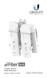
AF-MPx4
Brand: Ubiquiti Pages: 20

AM-34
Brand: Amprobe Pages: 1

4220
Brand: Quick Eagle Networks Pages: 3

C-72
Brand: Work Pro Pages: 20

VersiVision FVRM880 Series
Brand: Versitron Pages: 12

VR-9807A
Brand: Victor Pages: 28

UD77
Brand: Urrea Pages: 24

16E1
Brand: Techroutes Pages: 16


