background image

AD-75HS

Installation Manual

081398GS/abe

ADC

 Part No. 113039

For replacement parts, contact the distributor from which the dryer

was purchased or

American Dryer Corporation

88 Currant Road

Fall River MA 02720-4781

Telephone: (508) 678-9000  /  Fax: (508) 678-9447

E-mail: [email protected]

(Gas/Electric/Steam)
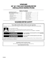
WARNING:

For your safety the information in this manual must be

followed to minimize the risk of fire or explosion or to

prevent property damage, personal injury or death.

Do not store or use gasoline or other flammable vapor

and liquids in the vicinity of this or any other

appliance.

WHAT DO YOU DO IF YOU SMELL GAS

* Do not try to light any appliance.

* Do not touch any electrical switch; do not use any phone in your

building.

* Clear the room, building or area of all occupants.

* Immediately call your gas supplier from a neighbor's phone.

Follow the gas supplier's instructions.

* If you cannot reach your gas supplier, call the fire department.

Installation and service must be performed by a qualified installer,

service agency or the gas supplier.

Summary of Contents for Gas/Electric/Steam AD-75HS

Page 1: ... prevent property damage personal injury or death Do not store or use gasoline or other flammable vapor and liquids in the vicinity of this or any other appliance WHAT DO YOU DO IF YOU SMELL GAS Do not try to light any appliance Do not touch any electrical switch do not use any phone in your building Clear the room building or area of all occupants Immediately call your gas supplier from a neighbo...

Page 2: ...notice or obligation in prices specifications colors and material and to change or discontinue models Important For your convenience log the following information Replacement parts can be obtained from your distributor or the ADC factory When ordering replacement parts from the factory you can FAX your order to ADC at 508 678 9447 or telephone your orders directly to the ADC Parts Department at 50...

Page 3: ...r OSHA Occupational Safety and Health Administration STANDARDS CAUTION LABEL ALL WIRES PRIOR TO DISCONNECTION WHEN SERVICING CONTROLS WIRING ERRORS CAN CAUSE IMPROPER AND DANGER OUS OPERATION DRYER S SHOULD NEVER BE LEFT UNATTENDED WHILE IN OPERATION CAUTION VERIFY PROPER OPERATION AFTER SERVICING WARNING The dryer must never be operated with any of the back guards outer tops or service panels rem...

Page 4: ... DRY MOP HEADS IN THE DRYER DO NOT USE DRYER IN THE PRESENCE OF DRY CLEANING FUMES IMPORTANT PLEASE OBSERVE ALL SAFETY PRECAUTIONS displayed on the equipment and or specified in the installation operator s manual included with the dryer Dryer s must not be installed or stored in an area where it will be exposed to water and or weather ...

Page 5: ...ting Up 11 C Dryer Enclosure Requirements 12 D Fresh Air Supply 13 E Exhaust Requirements 14 F Electrical Information 18 G Gas Information 26 H Steam Information 30 I Preparation For Operation Start up 35 J Preoperational Tests 36 K Preoperational Instructions 38 L Shut Down Instructions 39 SECTION IV SERVICE PARTS INFORMATION 40 A Service 40 B Parts 40 SECTION V WARRANTY INFORMATION 41 A Returnin...

Page 6: ...45 SECTION VII PROCEDURE FOR FUNCTIONAL CHECK OF REPLACEMENT COMPONENTS 46 SECTION VIII REVERSING TIMER SPIN DWELL ADJUSTMENTS 49 SECTION IX TECHNICAL INFORMATION 50 Data Label 51 SECTION X TROUBLESHOOTING 52 Microprocessor Computer Models 54 Dual Timer Models 64 ...

Page 7: ...beaccepted butthenumberreceivedandthenumberrefusedmustbenoted onthereceipt 4 Ifyoudeterminethatthedryerwasdamagedafterthetruckerhasleftyourlocation youshouldcallthe delivering carrier s freight terminal immediately and file a claim The freight company considers this concealeddamage Thistypeoffreightclaimisverydifficulttogetpaidandbecomesextremelydifficult whenmorethanadayortwopassesafterthefreight...

Page 8: ... call your gas supplier from a neighbor s phone Follow the gas supplier s instructions f If you cannot reach your gas supplier call the fire department 4 Installation and service must be performed by a qualified installer service agency or gas supplier 5 Dryer s must be exhausted to the outdoors 6 Although ADC produces a very versatile machine there are some articles that due to fabric composition...

Page 9: ... left in the dryer after the drying and cooling cycles have been completed can create a fire hazard 12 DO NOT operate steam dryers with more than 125 PSI steam pressure Excessive steam pressure can damage steam coil and or harm personnel 13 Replace leaking flexible hoses or other steam fixtures immediately DO NOT operate the dryer with leaking flexible hoses PERSONAL INJURY MAY RESULT 14 The norma...

Page 10: ...notice or obligation 0 080 3 7 5 W OEV NJ 6 7 0 7 5 FP 6 7 37 FP 6 7 02725 3 NZ 225 23 1 1 LDPHWHU FP 6 7 92 80 FX IW FX P 5 56 3 5 217 1 5 5 56 3 5 758 92 7 9 Y 3352 7 8QFUDWHG OEV NJ 3352 7 UDWHG OEV NJ 7 1387 EWX KU NFDO KU 5 2 FIP FPP 1 7 3 3 6 FP 92 7 9 Y 3352 7 81 5 7 OEV NJ 3352 7 5 7 OEV NJ 5 2 FIP FPP 92 7 9 Y 3352 7 81 5 7 OEV NJ 3352 7 5 7 OEV NJ 5 2 FIP FPP 2035 66 5 92 80 FIK FPK 5 21...

Page 11: ...7 Specifications ADG 75HS ADE 75 ADS 75 NOTE ADC reserves the right to make changes in specifications at any time without notice or obligation ...

Page 12: ...Dryer Front View Illus No Description 1 Controls 2 Control top access Door Assembly 3 Main Door Assembly 4 Lint Compartment Area lint screen located behind door 5 Data Label and Installation Label located behind control service door ...

Page 13: ... 8 Compressed Air Supply Inlet behind Electric Service Relay Box for steam units Only 3 Electric Service Relay Box 4 Tumbler Bearing Mount Assembly 5 Idler Bearing Mount Assembly 6 Blower Motor Assembly 7 Leveling Leg rear 8 Basket Drive Motor Assembly Reversing Models Only 9 Dryer Exhaust Electric service connections for Gas Models and Steam Models are made in this box ...

Page 14: ...floor area that the dryer is to rest on 2 The dryer must not be installed or stored in an area where it will be exposed to water and or weather 3 The dryer is for use in noncombustible locations 4 Provisions for adequate air supply must be provided as noted in this manual refer to Fresh Air Supply in Section D 5 Clearance provisions must be made from combustible construction as noted in this manua...

Page 15: ...ts located in the lint chamber area remove the lint door With the skid removed to make it easier to slide the dryer into its final position slightly lower ALL four 4 leveling legs so that the dryer will slide on the legs instead of the base frame To increase bearing life and improve efficiency the dryer should be tilted slightly to the rear The lint coops of ALL AD 75 dryers are supported during s...

Page 16: ...allowance must be made for opening and closing of the control door and the lint door It is suggested that the dryer be positioned about two 2 feet away from the nearest obstruction for ease of installation maintenance and service to be measured from the back guard Refer to the illustration above for details NOTE Air considerations are important for proper and efficient operation IMPORTANT Even tho...

Page 17: ... is required for each dryer To compensate for the use of registers or louvers used over the openings this make up air must be increased by approximately thirty three percent 33 Make up air openings should not be located in an area directly near where exhaust vents exit the building It is not necessary to have a separate make up air opening for each dryer Common make up air openings are acceptable ...

Page 18: ...nalareaof theductworkmustbeincreased ALL ductworkshouldbesmoothinsidewithnoprojectionsfromsheetmetalscrewsorotherobstructions whichwillcollectlint Whenaddingducts theducttobeaddedshouldoverlaptheducttowhichitistobe connected ALLductworkjointsmustbetapedtopreventmoistureandlintfromescapingintothebuilding Inspectiondoorsshouldbeinstalledatstrategicpointsintheexhaustductworkforperiodicinspectionand c...

Page 19: ...ngleDryerVenting Wherepossible itissuggestedtoprovideaseparateexhaustductforeachdryer Theexhaustductshould belaidoutinsuchawaythattheductworktravelsasdirectlyaspossibletotheoutdoorswithasfewturns aspossible Itissuggestedthattheuseof90 turnsintheductingbeavoided use30 and or45 angles instead Theshapeoftheexhaustductworkisnotcriticalsolongastheminimumcrosssectionareais provided IMPORTANT Minimumduct...

Page 20: ...d at strategic points in the exhaust duct work for periodic inspection and clean out of lint from the duct work NOTE Where the exhaust duct passes through a wall ceiling or roof made of combustible materials the opening must be 2 inches larger all the way around than the duct The duct must be centered within this opening a Outside Duct Work Protection 1 To protect the outside end of horizontal duc...

Page 21: ...17 ...

Page 22: ...ANT Failure to comply with these codes or ordinances and or the requirements stipulated in this manual can result in personal injury or component failure NOTE Component failure due to improper installation will VOID THE WARRANTY Each dryer should be connected to an independently protected branch circuit The dryer must be connected with copper wire only DO NOT use aluminum wire which could cause a ...

Page 23: ...40 VAC ARE NOT THE SAME Any damage done to dryer components due to improper voltage connections will automatically VOID THE WARRANTY NOTE ADC reserves the right to make changes in specifications at any time without notice or obligation ADG 75HS GAS ADS 75 STEAM 03257 17 9 DQG 9 5 127 7 6 0 KHQ RUGHULQJ VSHFLI H DFW YROWDJH 127 XVH UDWLQJV DUH GXDO HOHPHQW WLPH GHOD FXUUHQW OLPLWLQJ FODVV 5 RU 5 21...

Page 24: ...ARE NOT THE SAME Any damage done to dryer components due to improper voltage connections will automatically VOID THE WARRANTY NOTE 3 Phase 3ø figures shown are for three 3 wire service ONLY NOTE ADC reserves the right to make changes in specifications at any time without notice or obligation b Electric Models ONLY ADE 75 ELECTRIC 03257 17 9 DQG 9 5 127 7 6 0 KHQ RUGHULQJ VSHFLI H DFW YROWDJH 127 X...

Page 25: ... metal connection all the way to the electrical ground If there are any non metallic interruptions such as a meter pump plastic rubber or other insulating connectors they must be jumped out with no 4 copper wire and securely clamped to bare metal at both ends IMPORTANT For personal safety and proper operation the dryer must be grounded Provisions are made for ground connection in each dryer at the...

Page 26: ...nections Hookup for Non Reversing Models Only The electrical connections on ALL 3 phase 3ø gas and steam dryers are made into the rear service box located at the upper left area of the dryer Electrical connections for electrically heated dryers are made in the electric oven area located at the upper rear area of the dryer NOTE A CIRCUIT SERVING EACH DRYER MUST BE PROVIDED If local codes permit pow...

Page 27: ...hase 1ø input connection is required on a 3 phase 3ø dryer For gas and steam dryers manufactured for operation at 3 phase 3ø the electrical connections are made at the power distribution block located in the service box at the rear upper left corner of the dryer The ground connection is made to the copper lug also provided in this box To gain access to the service box contactor the service box cov...

Page 28: ...dryer can be hard wired directly to the service breaker panel In ALL cases a strain relief must be installed where the wiring enters the dryer For gas dryers and steam dryers manufactured for operation at 3 phase 3ø the electrical connections are made at the power distribution block located in the service box at the rear upper left corner of the dryer The ground connection is made to the copper lu...

Page 29: ...ST BE GROUNDED Aground lug has been provided for this purpose Input connection wiring must be sized properly to handle the dryer s current draw This information is printed on the dryers data label IMPORTANT A separate circuit serving each dryer must be provided The electrical input connections are made at the electric oven contactor located inside the assembly at the rear center upper section of t...

Page 30: ...pply as noted can cause irreparable damage to the gas valve which will VOIDTHEWARRANTY WARNING FIRE or EXPLOSION COULD RESULT 1 Gas Supply The gas dryer installation must meet the American National Standard National Fuel Gas Code ANSI Z223 1 LATEST EDITION as well as local codes and ordinances and must be done by a qualified professional NOTE Undersizedgaspipingwillresultinignitionproblems slowdry...

Page 31: ...the gas pressure must be regulated upstream of the dryer The pressure measured at each gas valve pressure tap must be a consistent 11 0 inches water column W C There is no regulator or regulation provided in an L P dryer The water column W C pressure must be regulated at the source L P tank or an external regulator must be added to each dryer D M S Drill Material Size of equivalents are as follows...

Page 32: ...The minimum pipe size supply line to the dryer is 3 4 N P T For ease in servicing the gas supply line of each dryer must have its own shut off valve The size of the main gas supply line header will vary depending on the distance this line travels from the gas meter or in the case of L P liquid propane gas the supply tank other gas operated appliances on the same line etc Specific information regar...

Page 33: ...e joint compounds that resist the action of natural gas and L P gas must be used IMPORTANT Test ALL connections for leaks by brushing on a soapy water solution liquid detergent works well WARNING NEVER TEST FOR LEAKS WITH A FLAME ALL components materials must conform to National Gas Code specifications It is important that gas pressure regulators meet applicable pressure requirements and that gas ...

Page 34: ...H STEAM INFORMATION It is your responsibility to have ALL plumbing connections made by a qualified professional to assure that the steam plumbing installation is adequate and conforms with local and state regulations or codes IMPORTANT Failuretocomplywiththerequirementsstipulatedinthismanualcanresultin componentfailurewhichwillVOIDTHEWARRANTY NOTE The ADS 75 is manufactured with a pneumatic piston...

Page 35: ...coil as possible 1 A trap with capacity of 700 pounds of condensate per hour at 125 psi is needed for each unit f The supply line and the return line should be insulated This will save energy and provide for the safety of the operator and maintenance personnel g Water pockets in the supply line caused by low points will provide wet steam to the coil possibly causing steam coil damage ALL horizonta...

Page 36: ...e electric service relay box b Air Connection Air connection to system 1 8 inch N P T c No air regulator or filtration is provided with the dryer External regulation filtration of 80 psi must be provided It is suggested that a regulator filter gauge arrangement be added to the compressed air line just before the dryer connection This is necessary to insure that correct and clean air pressure is ac...

Page 37: ...viding instant heat to start the drying process When the damper is closed ambient air is drawn directly into the tumbler allowing a rapid cool down Diagram 2 Diagram 1 shows the damper in the heating open mode allowing heat into the tumbler Diagram 2 shows the damper in the cool down closed mode pulling ambient air directly into the tumbler without passing through the coils NOTE With the dryer off...

Page 38: ...djusted prior to shipping at 80 PSI steam damper operation must be checked before the dryer is put into operation Refer to the previous page page 33 for instructions to check steam damper operation If steam damper adjustment is necessary locate the flow control valve and make the necessary adjustments as noted below ...

Page 39: ...lled and adjusted at the factory prior to shipping However each sail switch adjustment must be checked to assure that this important safety control is functioning Refer to page 37 for Sail Switch Adjustment 5 GAS MODELS be sure that ALL gas shut off valves are in the open position 6 Be sure ALL side and base panels are on the dryer 7 Check ALL service doors to insure that they are closed and secur...

Page 40: ... diagnostics Ifignitionisnotestablishedwithinthreetimes theheatcircuitintheHSImodule will lock out until it is manually reset To reset the HSI system open and close the main door and restart the dryer A gas pressure test should be taken at the gas valve pressure tap of each dryer to assure that the water column pressure W C is correct and consistent NOTE Water column pressure requirements measured...

Page 41: ... components are functioning properly IMPORTANT The dryer basket tumbler is treated with a protective coating ADC suggests tumblingoldclothesormaterialinthebasket tumbler usingamilddetergentto removetheprotectivecoating 5 Make a complete operational check of ALL operating controls a For microprocessor model check controller computer programs selections 1 Each microprocessor controller computer has ...

Page 42: ...e Manual timed Mode b Dual Timer Models 1 Both dwell stop and basket tumbler spin time are adjustable Refer to the illustration on page 49 8 Check to insure that ALL set screws i e tumbler drive idler etc are tight K PREOPERATIONAL INSTRUCTIONS 1 To start the dryer a Microprocessor computer dryers 1 The L E D light emitting diode display will read FILL 2 Press the E on the touchpad of the keyboard...

Page 43: ... switch or the circuit breaker 2 Discontinue the heat supply a GAS MODELS discontinue the gas supply 1 SHUT OFF external gas supply shut off valve 2 SHUT OFF internal gas supply shut off valve located in the gas valve burner area b STEAM MODELS discontinue the steam supply 1 SHUT OFF external location furnished shut off valve 2 SHUT OFF internal steam valves in the supply lines and the return line...

Page 44: ...randserialnumbersothatyourinquiryishandledinanexpeditiousmanner B PARTS 1 Replacement parts should be purchased from the distributor from whom the ADC equipment was purchased If the distributor cannot be contacted or is unknown contact the ADC Parts Department for a distributor in your area Parts may also be purchased directly from the factory by calling the ADC Parts Department at 508 678 9000 or...

Page 45: ...stributor cannot be contacted or is unknown warranty information can be obtained from the factory by contacting the ADC Warranty Department at 508 678 9000 NOTE Whenever contacting the ADC factory for warranty or warranty information be sure to have the dryer s model number and serial number available so that your inquiry can be handled in anexpeditiousmanner C RETURNING WARRANTY PARTS ALL dryer o...

Page 46: ...d in transit Damage claims are the responsibility of the shipper IMPORTANT No replacements credits or refunds will be issued for merchandise damaged in transit 5 ALL returns should be shipped to the ADC factory in such a manner that they are insured and a proof of delivery can be obtained by the sender 6 Shipping charges are not the responsibility of ADC ALL returns should be prepaid to the factor...

Page 47: ...G KEEPDRYERAREACLEARAND FREE FROM COMBUSTIBLE MATERIALS GASOLINE and OTHER FLAMMABLEVAPORS and LIQUIDS NOTE Suggested time intervals shown are for average usage which is considered six 6 to eight 8 operational running hoursperday SUGGESTED CLEANING SCHEDULE EVERY THIRD or FOURTH LOAD Clean the lint screen every third or fourth load A clogged lint screen will cause poor dryer performance The lint s...

Page 48: ...enings NOTE Topreventdamage avoidcleaningand ortouchingignitor flame probeassembly EVERY 6 MONTHS Inspect and remove lint accumulation in customer furnished exhaust duct work system and from dryers internal exhaust ducting NOTE THEACCUMULATIONOFLINTINTHEEXHAUSTDUCTWORKCAN CREATEAPOTENTIALFIREHAZARD NOTE DONOTOBSTRUCTTHEFLOWOFCOMBUSTIONandVENTILATIONAIR CHECKCUSTOMERFURNISHEDBACKDRAFTDAMPERSINTHEEX...

Page 49: ...shut off valves orifices and grounding connections Motor and drive belts should be examined Cracked or seriously frayed belts should be replaced Tighten loose V belts when necessary Complete operational check of controls and valves Complete operational check of ALL safety devices door switches lint drawer switch sail switch burner and hi limit thermostats ...

Page 50: ...g installation of the replacement microprocessor computer board reestablish power to the dryer b Start the drying cycle by pressing any of the preset cycle in letters A thru F c Verify that the motor s and heat indicator dots in the microprocessor computer L E D light emitting diode are on Refer to the illustration below ...

Page 51: ...r must stop and ALL output indicator lights on the back side of the microprocessor computer board must go out Refer to illustration above f Try to restart the dryer with the main door open g The microprocessor computer board s L E D light emitting diode display must read DOOR h Close the main door and restart the dryer i Functional check of microprocessor computer board is complete ...

Page 52: ...onds and then shut off h The Hot Surface Ignition HSI module will attempt two 2 additional ignition trials after which the HSI module will lock out and the red indicator light will flash continuously i Functional check of the Hot Surface Ignition HSI Module is complete 1 Replace the flame sensor wire from the S2 terminal to the HSI module a Upon completing installation of the replacement Hot Surfa...

Page 53: ...ic service box which is located in the upper rear area of the dryer Both the dwell stop time and basket tumbler spin time are adjustable by mode selection switches located on the electronic timer as noted in the illustration below 7 0 1 1 63 1 7 0 6ZLWFK 3RVLWLRQ 1XPEHU 7LPH LQ 6HFRQGV 6723 7 0 6ZLWFK 3RVLWLRQ 1XPEHU 9DOXHV VKRZQ DUH VHFRQG ...

Page 54: ... service parts information from ADC This information is on the data label located on the inside of the control door When contacting American Dryer Corporation please have the model number and serial number available SECTION IX TECHNICAL INFORMATION A DATA LABEL Contact American Dryer Corporation ...

Page 55: ...cular model 4 TYPE OF HEAT The type of heat describes the type heat for your particular dryer gas either natural gas or liquid propane L P or steam 5 HEAT INPUT for GAS DRYERS This describes the heat input in British Thermal Units per Hour BTUH 6 ORIFICE SIZE for GAS DRYERS Gives the number drill size used 7 ELECTRIC SERVICE This describes the electric service for your particular model 8 GAS MANIF...

Page 56: ...eturned to the factory IMPORTANT When replacing blown fuses the replacement must be of the exact rating as the fuse being replaced The information provided should not be misconstrued as a hand book for use by an untrained person in making repairs WARNING ALL SERVICE and TROUBLESHOOTING SHOULD BE PERFORMED BYA QUALIFIED PROFESSIONALor SERVICEAGENCY WARNING WHILE MAKING REPAIRS OBSERVE ALL SAFETYPRE...

Page 57: ...1 1 7 2 0 21 16 7 21 21 0 1 225 66 5 5 0 1 6 5 3 1 12 6 7 6 7 780 5 5 66 9 12 6 25 9 5 7 21 1 7 0 5 02 6 7 0 3 5 5 02725 2 6 127 67 57 5 9 02725 5 9 56 1 02 6 21 23 5 7 6 1 21 21 5 7 21 5 9 02725 23 5 7 6 25 0 187 6 7 1 67236 2 5 1 02725 5 9 56 1 02 6 21 2 6 127 67 57 2 5 1 02725 5 9 56 1 02 6 21 23 5 7 6 25 0 187 6 7 1 67236 2 5 02725 1 1 02725 5 9 56 1 02 6 21 27 2 127 67 57 7 1 81 7 6 127 23 5 ...

Page 58: ...essor controller computer motor indicator dot and relay output L E D light emitting diode indicator dots are on but motor output L E D indicator is off a Failed microprocessor controller computer C Drive motor Reversing Models ONLY operates in one direction only stops and restarts in the same direction 1 Failed reversing contactor relay 2 Failed arc suppressor A S board 3 Failed microprocessor con...

Page 59: ...motor Reversing Models ONLY not operating does not start microprocessor computer motor indicator dots and relay output L E D light emitting diode indicators are on 1 Failed arc suppressor A S board 2 Failed contactors both blower fan impellor and drive 3 Failed motors both blower fan impellor motor and drive motor H Both drive motor and blower impellor fan motor Reversing Models ONLY not operating...

Page 60: ...it in main door lint drawer switch circuit a Main door not closed all the way b Main door switch is out of proper adjustment c Failed lint main door switch d Broken wire connection in main door wiring circuit 2 Failed 24 VAC step down transformer L Microprocessor controller computer L E D light emitting diode display reads door and the microprocessor computer DOOR L E D indicator is on 1 Failed mi...

Page 61: ...ight emitting diode returns to FILL 1 Loose connection somewhere in the main power circuit to the microprocessor controller computer R Microprocessor controller computer L E D light emitting diode display reads SEFL 1 Rotational sensor circuit failure fault somewhere in the tumbler basket rotation or circuit a Tumbler basket not rotating 1 Broken or loose V belts 2 Failure in drive motor circuit r...

Page 62: ...irty 2 Restriction in the exhaust 3 No exhaust air flow a Failed impellor fan blower b Fault in blower impellor fan motor circuit for Reversing Models ONLY 2 Failed burner hi limit 3 Failed lint chamber sensor bracket basket tumbler hi limit switch ELECTRIC MODELS 1 Fault in sail switch circuit a Sail switch is out of adjustment or has failed b Sail switch damper is not closing or is fluttering 1 ...

Page 63: ...actor or Steam Model steam damper system 3 way micro valve GAS MODELS 1 Fault in Hot Surface Ignition HSI system a Ignitor glows but no ignition and HSI module LOCKS OUT red L E D light emitting diode indicator flashes 1 Flame probe assembly is out of adjustment or has failed 2 Severe air turbulence 3 Failed HSI module 4 Failed gas valve b Ignitor glows burner lights but burner goes off right away...

Page 64: ... mechanical motor b Steam damper stuck in closed position check for obstruction W Dryer operates but is taking too long to dry 1 Exhaust duct work run is too long or is undersized back pressure cannot exceed 0 3 inches water column W C 2 Restriction in duct work a Dryer back draft damper is sticking partially closed b Restriction obstruction in duct work 1 Check duct work from the dryer all the wa...

Page 65: ...lor fan blower is rotating in the wrong direction only for 3ø Models ONLY e Burner orifice size D M S drill material size too large for application i e high elevation 3 Sail switch is fluttering a Restriction in the exhaust 1 Lint screen is dirty or is not being cleaned often enough 4 Failed burner hi limit opens at incorrect temperature 5 Gas supply may have too low a heating value ELECTRIC MODEL...

Page 66: ...urate 10 Failed lint chamber hi heat switch thermostat opens at incorrect temperature 11 Microprocessor temperature sensor covered with lint X At the completion of the AUTO drying cooling cycle the load is coming out over dried 1 Percent of dryness dryness level of the cycle selected is too high 2 Factor A and Factor B is not set correctly or Factor B has to be adjusted for adverse local condition...

Page 67: ...d position BB Scraping noise at basket tumbler area 1 Check for obstruction caught in basket tumbler wrapper area 2 Basket tumbler is out of proper alignment a Check both the vertical alignment and lateral alignment b Check for gap between the front panel and basket tumbler bearing set screws may have come loose and basket tumbler walked forward or backward 3 Loose basket tumbler tie rod 4 Failed ...

Page 68: ...t of proper adjustment c Failed main door switch d Broken connection wire somewhere in the main door switch circuit 4 Failed push to start relay 5 Failed 24 VAC step down transformer or a fault in the wiring 6 Failed heat timer 7 Failed control step down transformer for 380 volts or higher models ONLY B Drive motor is not operating does not start 1 Failed drive motor contactor relay 2 Failed rever...

Page 69: ...out on internal overload protector a Motor air vents clogged with lint b Low voltage to motor c Failed motor d Failed blower impellor fan out of balance G Both drive motor and blower impellor fan motor Reversing Models ONLY not operating do not start and indicator light is on 1 Fault at L1 or L2 termination s between the terminal block and contactors relays 2 Failed contactors both blower fan impe...

Page 70: ...has failed b Sail switch damper is not closing or is fluttering 1 Lint screen is dirty 2 Restriction in the exhaust 3 No exhaust air flow a Failed impellor fan blower b Fault in blower impellor fan motor circuit c Failed oven hi limit d Failed lint chamber sensor bracket basket tumbler hi limit e Failed temperature selection switch or circuit f Failed temperature cycle thermostat try another selec...

Page 71: ...glows but burner goes off right away 1 Flame probe assembly is out of adjustment or has failed 2 Sail switch is fluttering a Lint screen is dirty b Restriction in exhaust duct work c Hot Surface Ignitor does not glow and HSI module LOCKS OUT red L E D light emitting diode indicator flashes 1 Fault in Hot Surface Ignitor wiring break or loose connection 2 Failed Hot Surface Ignitor 3 Failed HSI mod...

Page 72: ...bstruction in duct work 1 Check duct work from the dryer all the way to the outdoors 3 Insufficient make up air 4 Impellor fan blower is rotating in the wrong direction only for 3ø Models ONLY 5 Lint screen is dirty or is not being cleaned often enough 6 Inadequate air flow a Impellor fan blower failure GAS MODELS 1 Low and or inconsistent gas pressure Natural Gas pressure must be between 3 5 and ...

Page 73: ...direction only for 3ø Models ONLY 5 Failed electric element s 6 Sail switch is fluttering a Restriction in the exhaust b Sail switch is not adjusted properly STEAM MODELS 1 Low steam pressure 2 Insufficient make up air 3 Lint screen is dirty or is not being cleaned often enough 4 Restriction in the exhaust 5 Dirty steam coil a Fins are clogged with lint 6 Steam damper system is not functioning pro...

Page 74: ...eck for obstruction caught in basket tumbler wrapper area 2 Basket tumbler is out of proper alignment a Check both the vertical alignment and lateral alignment b Check for gap between the front panel and basket tumbler bearing set screws may have come loose and basket tumbler walked forward or backward 3 Loose basket tumbler tie rod 4 Failed basket tumbler support N Excessive noise and or vibratio...

Page 75: ...adjustment bolts hardware are loose 5 Failed basket tumbler support 6 Loose motor mount 7 Failed idler basket tumbler or blower drive bearings 8 V belts too tight or too loose 9 Bearing set screws either basket tumbler idler or blower shaft are loose 10 Failed motor bearing ...

Page 76: ...ADC113039 1 09 01 98 253 ...

Reviews: