background image

WVM 40-1450

Adsorption dryer

Operating manual

Revision 04—06_2018 /EN

Cod: 398H271785

Summary of Contents for Zander WVM 1080

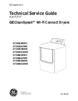
Page 1: ...WVM 40 1450 Adsorption dryer Operating manual Revision 04 06_2018 EN Cod 398H271785 ...

Page 2: ......

Page 3: ...nes 28 Connection of electrical components 29 Start up 30 Requirements for initial commissioning 30 Overview of the operating and display elements 30 Commissioning of the dryer 31 Preparation for commissioning 32 Monitoring dryer operation 35 Notes on specific operating situations 35 Shutdown and restart dryer 36 Emergency shutdown 36 Stopping the dryer 36 Depressurising and shutting down the drye...

Page 4: ...EN Operating manual 4 WVM 40 1450 Notes on error messages and errors 48 Appendix Technical Documents 49 Technical data overview of standard dryers 50 Spare parts list 52 ...

Page 5: ...r is obliged to enter missing unit data in the above table regularly update the unit data The above device specifications are necessary to quickly identify the dryer and its compo nents and facilitate servicing Other important data regarding the dryer such as permitted operation pressure and electrical power are found on the type plate For location of the type plate see page 8 ...

Page 6: ...lementary documents Supplementary documents such as operating manuals for options or pertaining components must always be heeded They contain additional information e g regarding maintenance and are therefore necessary for safe operation of the plant Notes on upstream and downstream filters Upstream and downstream filters are not contained in the standard scope of delivery of the dryer For this rea...

Page 7: ...l box Note These notes provide you with hints and information on the safe and efficient handling of machines and devices Warning These safety notes warn against damage to property and help you to avoid such damage Danger These danger notes with a grey background warn against personal injury and or danger to life and limb danger notes help you to avoid serious or life threa tening situations for you...

Page 8: ...s operated by non qualified personnel not used within its intended design specifications is repaired or maintained incorrectly Note For your own safety and to prevent machine damage please note the informa tion and safety notes in these operating instructions when working with the dryer Signs and danger zones at the dryer Signs and instructions 1 Type plate 2 Vessel plate Please note the above pla...

Page 9: ...nly released through expansion and relief valves can lead to serious injury Hot surfaces During operation certain surfaces of the dryer reach temperatures above 120 C At insulated dryers screw connections might protrude from the insulation Voltage Various parts of the dryer are live These components may only be connected opened and serviced by authorised technical personnel Risk of slipping During...

Page 10: ...d as a climbing aid Pipes valves and similar fittings have not been designed for such loads They could fracture tear off or become damaged in another way General safety notes For your own safety when carrying out any work on the dryer comply with all applicable national safety regulations Personnel qualification Only authorized and qualified specialist personnel may be tasked with the work on the d...

Page 11: ...st sudden air ejection During expansion the pressure is released suddenly through the muffler A loud cracking noise occurs which can injure your hearing Particles carried in the air can injure your eyes or skin Always wear eye and ear protection therefore when you are in the vicinity of the dryer Operate the dryer only within the permitted limits see type plate If the unit is operated under conditi...

Page 12: ...ing compressed air Never leave tools loose parts or cloths in at or on the dryer Following maintenance work always check all flange and bolt connections for leakage and secure seating Only use replacement parts that are suitable for the relevant function and meet the techni cal requirements stipulated by the manufacturer This is always the case if you use original replacement parts only Removal an...

Page 13: ... outlet valve l 7 Pressure transducer 2 Control air filter and pressure reducer 8 Vessel 3 Filler sleeve for desiccant 9 Dew point measuring chamber 4 Switch cabinet with operating panel 10 Pressure build up valve 5 Vessel pressure gauge 11 Discharge sleeve for desiccant 6 Stop valve for vessel pressure gauge 12 Main inlet valve ...

Page 14: ...ase button for the safety thermostat 1 Resistance thermometer for regeneration gas final temperature 6 Suction opening for regeneration gas 2 Vacuum pump 7 Heater 3 Lashing eye 8 Expansion valve with silencer 4 Regeneration gas outlet of the vacuum pum 9 Resistance thermometer for the control tem perature of the regeneration gas ...

Page 15: ...wo vessels alternate between different operating modes Whilst in one ves sel compressed air is de humidified adsorption in the other vessel the humid drying agent is prepared for another charge regeneration These two states which run in parallel during compressed air preparation are described below Adsorption The humid air is supplied through a compres sor and the inlet valve of the dryer The com ...

Page 16: ...cer as a low hum Expansion phase Heating phase duration several hours A vacuum pump sucks ambient air through the heater to the vessel to be regenerated The air is thereby heated by the heater The warm air subsequently flows through the humid desiccant removing the water contained in the agent which is fed out in the form of steam together with the air through the piping This can be either a steam...

Page 17: ...via the pressure build up line The vessel can now be switched from regeneration to absorption operation Pressure build up Stand by phase for dewpoint measurement option The regenerated vessel remains in the stand by phase as long as the pressure dewpoint is better than the set switch over value Switch over only occurs when the switch over value is reached or after a maximum cycle duration of 48 ho...

Page 18: ... The heater Adaptation for outdoor installation The standard dryer is designed for installation in confined places and not for outdoor opera tion because the following factors affect its function and service life Humidity from rain or other precipitation Corrosion due to high humidity or salt content in the ambient air Freezing of valves taps flaps and other components at low temperatures If you i...

Page 19: ...am heat exchanger comes with an appropriate steam shut off valve In this case the scope of delivery can also comprise supplementary documents such as data sheets or supplementary operating manuals Steam electric heater combination In this option the existing electric heater is supplemented by an additional steam heat ex changer This allows for three operating modes Pure steam operation Sufficient ...

Page 20: ...des Use these eyes to secure the unit during transport Only use suitable and technically perfect lifting gear with a sufficient carrying capacity During transportation the dryer must be carefully secured against falling over Remove the transport packaging at the installation site only and dispose of it in a proper manner The manufacturer will not be liable for any damage caused by incorrect storag...

Page 21: ...egeneration and a suitable pressure dew point A higher ambient temperature or relative humidity must be specially considered when designing the dryer and recorded in the offer document if this proves to be unfeasible If the required cooling water is available you should implement the optional loop cooler Please also heed the appropriate notes in section Technical data Ventilation Provide sufficien...

Page 22: ...es The dryer should be erected with sufficient clearance above to the sides and behind so that maintenance work can be carried out and the drying agent can be changed without hindrance see illustration Required clearances at the top and the sides of the unit minimum 1 m Lifting devices You should have lifting devices with an ade quate load capacity available for assembling and maintaining individu...

Page 23: ...t the vessel top to lift the dryer Remove packaging Attach suitable lifting gear to the lifting eyes on the vessels see Item 1 on the adjacent illustration The lashing eyes Item 2 are intended to secure the unit during transport and are not suited to lift the dryer Lifting and lashing eyes at vessel Note The vessels are filled with layers of various desiccants They should therefore be transported i...

Page 24: ...se cover dryer with a tarpaulin The ambient temperature in the storage room may not be below 1 ºC To storage the dryer proceed as follows Decommission dryer as described on page 36 Ensure that the inlet valve and the outlet valve installed on the site are closed and release all pressure from the dryer Make sure that existing steam valves with optional steam heat exchanger or cooling water valves w...

Page 25: ...and storage WVM 40 1450 25 Note To recommission the dryer after prolonged storage please proceed as descri bed for initial commissioning see page 31 Store drying agents Do not store drying agents in the open air Protect drying agents against humidity ...

Page 26: ...e requirements described here are not met This can also degrade the dryer s function For proper installation the operator must provide the following Connections and lines must be provided for compressed air intake and exit The operator must install shut off valves for compressed air and supply media at the intakes and exits All pipelines couplings and connections must have the correct diameter and...

Page 27: ...to pre vent foreign objects or animals from entering the dryer The outlet line must be installed in such a way that there is no risk of injury from hot regeneration gas Rainguard when lines point upwards Rainguard when line exits to the side If both an inlet and an outlet line are installed ensure that the escaping hot regener ation gas is not again drawn into the inlet line The outlet opening of ...

Page 28: ...to the compressed air system while heeding rated diameter and pressure The figure below shows a proper installation Compressed air system Item Component 1 Dryer 2 Humid air inlet 3 Compressed air inlet valve 4 Preliminary filter 5 Bypass line 6 Valve in bypass line 7 Bypass filter 8 Valve at outlet of bypass filter 9 Afterfilter 10 Compressed air outlet valve 11 Dry air outlet Example of a proper ...

Page 29: ...he terminal strip the circuit diagram is attached inside the switch cabinet Connect the dryer s earth cable to the PE terminal Protect the dryer against short circuits by installing fuses to all phases Cable recess in switch cabinet base and terminal connections for power supply Connection of dryer to the fault signalling system There is an ex works option to connect the dryer to a fault signallin...

Page 30: ...sed air can flow through the dryer Operators for the components are available Inspection to be carried out prior to commissioning all pipe cable and screw connections have been retightened none of the lines are worn at edge of the dryer body all connections are properly secured the electric connections are properly secured and in good condition the operator supplied components such as safety valve...

Page 31: ...ated to temperatures of over 120 C At insulated dryers screw connections might protrude from the insulation Do not touch hot surfaces Allow surfaces to cool before you carry out any work at the dryer Risk of injury from suddenly escaping gas While the unit is under pressure never remove any components or otherwise interfere with the dryer Suddenly escaping gases can lead to serious injury Prior to...

Page 32: ...e pressure increase at the vessel pressure gauge see page 13 In one of the vessels the pressure must be increased until it reaches the operating pressure Compressed air inlet to the dryer Avoid abrupt pressure drop Avoid abrupt pressure drops by all means Too fast a pressure drop or too high flow rates can cause damage to the dryer For this reason make sure to open the pressure outlet valve only sl...

Page 33: ... colour of the housing and extends over several cooling fins Wait until the vacuum pump is fully started Then stop the dryer The fan wheel continues rotating for a short period of time During this time the assistant must check whether the wheel rotates in the correct direction The vacuum pump direction is correct if the fan wheel rotates in the direction of the arrow Procedure if direction of rota...

Page 34: ...see above Commissioning of dryer Set main switch to position I Start dryer see the operating manual for the controller The unit is now fully switched on provided that no error message is displaye How to proceed if an error message is displayed Warning In an emergency and in the event of safety related faults e g a sudden escape of compressed air defective components take the plant out of operation...

Page 35: ... This is the case if the operating parameters match or slightly fall below the specified values Dryer performance can degrade if the dryer often operates at part load Dryer performance increases as soon as the load is raised Part load operation can occur due to too low flow rates 30 of rated value by operating the plant with predried air i e the relative humidity of supply compressed air is below ...

Page 36: ...lve The dryer is now shut down Restart the dryer only after having eliminated all errors Stopping the dryer Please proceed as follows if no compressed air is needed at night or at weekends When the compressor remains on Close compressed air outlet valve Leave the customer s intake valve for compressed air open see installation example on page 28 Stop the dryer see the operating manual for the cont...

Page 37: ... regenerated at the same time Depressurise the adsorbing vessel e g by opening the manual drain valve on the downstream filter Wait until the pressure on the vessel pressure gauge of the adsorbing vessel has dropped to 0 bar Using the vessel pressure gauge check whether both vessels have been depressurised For maintenance work wait until the dryer has cooled down Risk of injury from hot surfaces C...

Page 38: ...g manual for the controller If necessary slowly open the compressed air inlet and outlet valves installed by the operator The dryer is now ready for operation and continuous automatic cycle If compressed air system and dryer have not remained at operating pressure If disconnected reconnect the voltage supply of the dryer Pressurise and switch on the dryer as described in the section on page 31 The...

Page 39: ... maintenance work only when the plant has been shut down and depressur ised Bolt connections must be undone with care Note ram pressure values Otherwise emerging media may cause personal injury Do not modify the factory settings of the control system in any way without prior consulta tion with the manufacturer Never carry out welding work on a vessel or modify the same in any way Following mainten...

Page 40: ...new 42 Vacuum pump Inspect bearing and replace if necessary 44 Dust filter Check dust filter for contamination and clean if necessary 44 Desiccant Check desiccant for contamination and replace if necessary 44 Preliminary and afterfilter optional Please refer to the manuals of the installed filters for details on the maintenance tasks to perform When carrying out any maintenance work please observe...

Page 41: ...the dryer and shut it down see page Depressurising and shutting down the dryer 37 Dam pressure can be caused by a blocked muffler a malfunction of the expansion valve a leaking pressure build up valve The respective necessary maintenance measures are described in the following sections Monthly maintenance Inspect intake opening for regeneration gas The regeneration gas is fed to the system through...

Page 42: ...jure persons and damage property Silencer elements should therefore be checked annually and replaced if soiled Beware of sudden air blast Pressure suddenly escapes via the silencer during expansion A loud expansion noise occurs which may damage your hearing Particles carried along with the air flow can damage your eyes or skin For this reason you must always wear eye and hearing protection when you...

Page 43: ... on the actual application and might thus be extended accordingly Warning The dew point sensor is a sensitive measuring device It can be damaged if subjected to forceful vibrations or shocks Therefore please handle the dew point sensor with great care at all times In order to limit the impact on the dryer operation to a minimum we recommend that you contact the manufacturer well in advance for con...

Page 44: ...ridges and the vessels We therefore recommend that you carry out these tasks together Note In accordance with national regulations a pressure vessel inspection may be prescribed to be carried out at regular intervals by an independent supervisory office For an inspection of the pressure vessels the drying agent must be removed as described as follows When inspecting the pressure vessels it is recom...

Page 45: ...5 years Under favourable conditions the desiccant might not have to be replaced at that stage and can be used for longer period see also page 21 However the service life depends greatly on the contamination of the compressed air or the effectiveness of the preliminary compressed air filter respectively and the contamination of the ambient air at the site Oil dust and dirt particles tend to deposit...

Page 46: ...ht be contami nated with pollutants Please take this into account when disposing of the desiccant Notes on the disposal of used desiccant As the used desiccant is contaminated with various substances its properties differ from those of new desiccant For this reason the manufacturer or supplier of desiccant cannot give any information on the used product Deliver used desiccant to a controlled dumpi...

Page 47: ... make sure to heed the next step Use a funnel if neces sary Unscrew the sleeve plug Make sure to compact the filling in the vessel Equip the sleeve plug with a non locking thread seal and screw in Repeat the procedure for the second vessel Restart the dryer if no other maintenance work is required Operate the dryer for two cycles then shut it down again Replace silencer as described on page 42 and...

Page 48: ...rmostat V Vacuum pump Notes on error messages and errors The error message from the dryer are displayed on the operating panel The controller manual provides appropriate information You are given information on the possible causes for the error and tips how to eliminate the error If the dryer is connected to a fault signalling system all error messages are transmitted through the potential free bu...

Page 49: ...hnical Documents The appendix of this operating manual contains the following technical documents and data Technical data List of service and desiccant kits Process diagram Pneumatic diagram of the control air unit Dimension drawing Electrical diagrams Declaration of Conformity ...

Page 50: ... 400 300 25 WVM 150 1500 1350 18 20 1300 470 375 25 WVM 200 1980 1782 23 70 1650 656 550 25 WVM 235 2350 2115 36 70 2000 827 750 25 WVM 300 2930 2637 36 70 2250 910 750 25 WVM 355 3550 3195 43 70 2650 1178 900 25 WVM 410 4100 3690 43 70 3250 1348 900 25 WVM 475 4740 4266 48 70 3650 1652 1150 25 WVM 525 5250 4725 63 20 4050 1718 1460 25 WVM 620 6210 5589 73 20 4700 2153 1460 25 WVM 710 7100 6390 84...

Page 51: ...ing to other Typ WVM 40 WVM 1450 Fluid class according to PED 2 Supply voltage see type plate Protection class IP54 min max Operating overpressure bar see type plate Ambient temperature C 1 50 Max intake temperature for regeneration air C please heed the table below that relates the moisture of the intake air to the temperature 1 40 Max dust contents of the regeneration air mg m3 50 Noise level 3 ...

Page 52: ...ves wear parts kit for the expansion valve V5 wear parts kit for the pressure build up valve V4 SKW410 W710 VM4 24 WVM 410 710 24 month SKW800 W1080 VM4 24 WVM 800 1080 24 month SKW1230 W1450 VM4 24 WVM 1230 1450 24 month SKW40 W50 VM4 E 48 WVM 40 50 48 month Control air filter element magnet valve wear parts kit for the expansion valve V5 wear parts kit for the pressure build up valve V4 wear par...

Page 53: ...M50DESMIX WVM 475 WVM475DESMIX WVM 65 WVM65DESMIX WVM 525 WVM525DESMIX WVM 85 WVM85DESMIX WVM 620 WVM620DESMIX WVM 120 WVM120DESMIX WVM 710 WVM710DESMIX WVM 150 WVM150DESMIX WVM 800 WVM800DESMIX WVM 200 WVM200DESMIX WVM 920 WVM920DESMIX WVM 235 WVM235DESMIX WVM 1080 WVM1080DESMIX WVM 300 WVM300DESMIX WVM 1230 WVM1230DESMIX WVM 355 WVM355DESMIX WVM 1450 WVM1450DESMIX ...

Page 54: ...200W 1 Flat gasketsDN200 WVM 1230 1450 GASKIT250W 1 Flat gasketsDN250 WVM 40 355 SDD 25 AL 1 Silencers WVM 410 1080 SDD 25 AL 2 Silencers WVM 1230 1450 SDD 40 AL 6 Silencers WVM 40 1450 ZHM100 450 1 dewpoint sensor WVM 40 50 RKSCD F40 16 VA 1 flow distributors WVM 65 80 RKSCD F50 16 VA 1 flow distributors WVM 120 200 RKSCD F80 16 VA 1 flow distributors WVM 235 355 RKSCD F100 16 VA 1 flow distribut...

Page 55: ......

Page 56: ...ico MI Italy Sede Operativa Gas Separation and Filtration Division EMEA Strada Zona Industriale 4 35020 S Angelo di Piove PD Italy tel 39 049 971 2111 fax 39 049 9701911 Web site www parker com hzd e mail technical support hiross parker com A division of Parker Hannifin Corporation ...

Reviews: