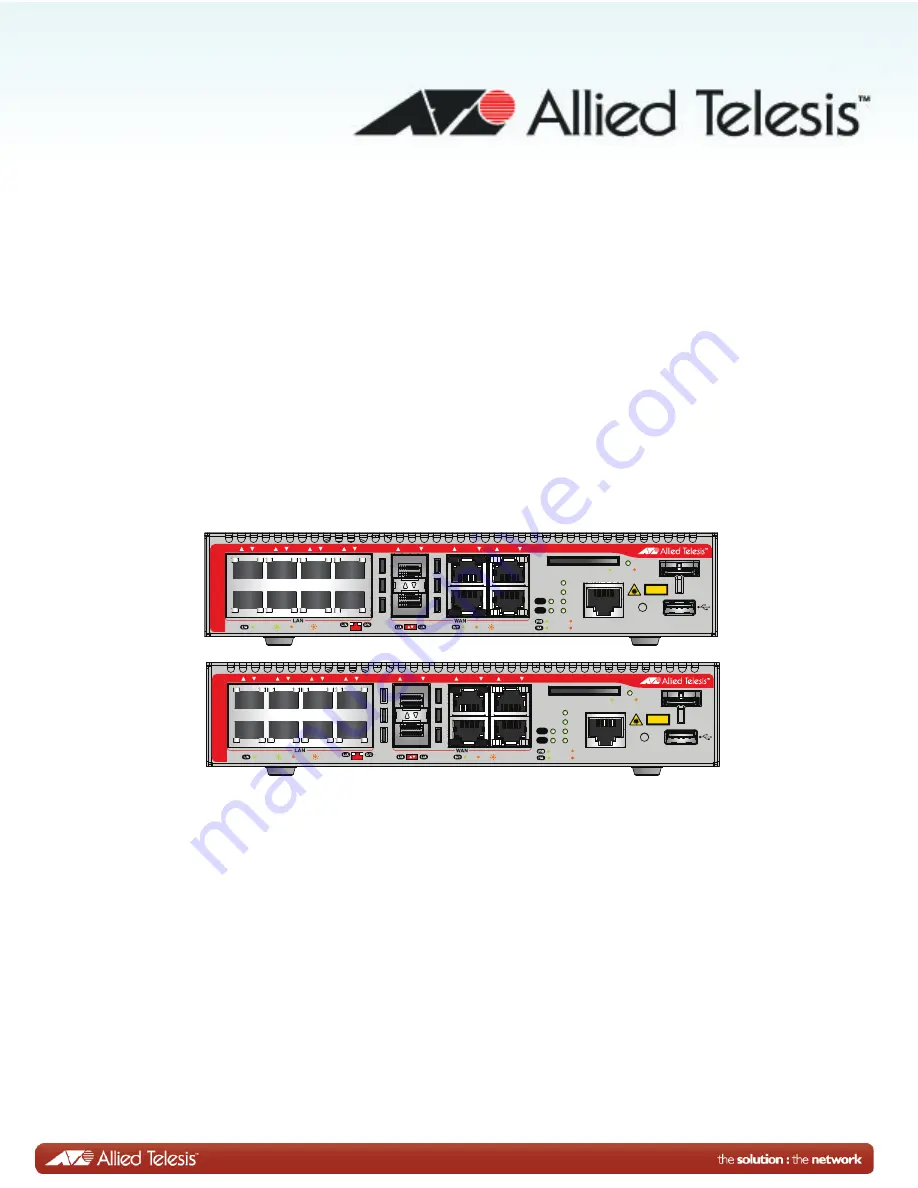
background image

C613-04069-00 REV A

AT-AR3050S

AT-AR4050S

Installation Guide 

CLASS 1

LASER PRODUCT

CONSOLE

SD

SD

FAULT

PWR

FNC1

FNC2

RESET

1

2

3

4

5

6

7

8

1

2

BYPASS

1

2

1

2

USB

HA

FDX

HDX

COL

READY

FAULT

READY

FAULT

MASTER

STANDBY

ETH

ETH

AR3050S

1000 LINK

ACT

100 LINK

ACT

AR3050S

CLASS 1

LASER PRODUCT

CONSOLE

SD

SD

FAULT

PWR

FNC1

FNC2

RESET

1

2

3

4

5

6

7

8

1

2

BYPASS

1

2

1

2

USB

HA

FDX

HDX

COL

READY

FAULT

READY

FAULT

MASTER

STANDBY

ETH

ETH

AR4050S

1000 LINK

ACT

100 LINK

ACT

Summary of Contents for AT-AR3050S

Page 1: ...5 6 7 8 1 2 BYPASS 1 2 1 2 USB HA FDX HDX COL READY FAULT READY FAULT MASTER STANDBY ETH ETH AR3050S 1000 LINK ACT 100 LINK ACT AR3050S CLASS 1 LASER PRODUCT CONSOLE SD SD FAULT PWR FNC1 FNC2 RESET 1 2 3 4 5 6 7 8 1 2 BYPASS 1 2 1 2 USB HA FDX HDX COL READY FAULT READY FAULT MASTER STANDBY ETH ETH AR4050S 1000 LINK ACT 100 LINK ACT ...

Page 2: ...respective owners Allied Telesis Inc reserves the right to make changes in specifications and other information contained in this document without prior written notice The information provided herein is subject to change without notice In no event shall Allied Telesis Inc be liable for any incidental special indirect or consequential damages whatsoever including but not limited to lost profits ari...

Page 3: ...mercial environment This equipment generates uses and can radiate radio frequency energy and if not installed and used in accordance with this instruction manual may cause harmful interference to radio communications Operation of this equipment in a residential area is likely to cause harmful interference in which case the user will be required to correct the interference at his own expense Note M...

Page 4: ...4 Translated Safety Statements Important Safety statements that have the symbol are translated into multiple languages in the Translated Safety Statements document at www alliedtelesis com support ...

Page 5: ...ment Panel 21 Management Software 22 Twisted Pair Ports 23 WAN Ports 24 ETH Ports RJ 45 24 ETH Ports SFP 24 Bypass Ports 24 LEDs 26 Power LED 26 Fault LED 26 High Availability LED 27 USB LED 28 SD Card LED 29 LEDs for the ETH 1 and ETH 2 Ports RJ 45 30 LEDs for the Twisted Pair LAN Ports 31 LEDs for the ETH 1 and ETH 2 Ports SFP 33 Function 1 LED 33 Function 2 LED 34 USB Port 35 USB Retainer Slot ...

Page 6: ...Chapter 4 Cabling the Networking Ports 67 Cabling the Twisted Pair Ports 68 Chapter 5 Troubleshooting 73 Appendix A Technical Specifications 77 Physical Specifications 77 Environmental Specifications 77 Power Specifications 78 Certifications 78 RJ 45 Twisted Pair Port Pinouts 79 RJ 45 Style Serial Console Port Pinouts 80 ...

Page 7: ...ip into the retaining bracket 52 Figure 26 Attaching the rubber feet 54 Figure 27 Turning the router upside down 55 Figure 28 Removing the rubber feet 56 Figure 29 Attaching handles to the brackets 56 Figure 30 Attaching the equipment rack brackets 57 Figure 31 Mounting the router horizontally in an equipment rack 57 Figure 32 Attaching the wall mount brackets to the side of the router 59 Figure 3...

Page 8: ...Figures 8 ...

Page 9: ...d Pair LAN Ports 32 Table 8 LEDs for ETH 1 and ETH 2 ports SFP 33 Table 9 Product Dimensions 77 Table 10 Product Weights 77 Table 11 Environmental Specifications 77 Table 12 Maximum Power Consumptions 78 Table 13 Input Voltages 78 Table 14 Product Certifications 78 Table 15 Pin Signals for 10 and 100 Mbps 79 Table 16 Pin Signals for 1000 Mbps 79 Table 17 RJ 45 Style Serial Console Port Pin Signals...

Page 10: ...Tables 10 ...

Page 11: ...ce This guide contains the installation instructions for the AT AR3050S and AT AR4050S routers This preface contains the following sections Document Conventions on page 10 Contacting Allied Telesis on page 11 ...

Page 12: ...ntions Note Notes provide additional information Caution Cautions inform you that performing or omitting a specific action may result in equipment damage or loss of data Warning Warnings inform you that performing or omitting a specific action may result in bodily injury ...

Page 13: ...ts to learn about RMAs and to contact Allied Telesis technical experts USA and EMEA phone support Select the phone number that best fits your location and customer type Hardware warranty information Learn about Allied Telesis warranties and register your product online Replacement Services Submit a Return Merchandise Authorization RMA request via our interactive support center Documentation View t...

Page 14: ...Preface 12 ...

Page 15: ...age 14 Front and Back Panels on page 15 Management Panel on page 17 Management Software on page 18 Twisted Pair Ports on page 19 WAN Ports on page 20 LEDs on page 22 USB Port on page 31 USB Retainer Slot on page 32 SD Card Slot on page 35 Console Port on page 36 Reset Button on page 37 Power Supply on page 38 ...

Page 16: ...ts Here are the basic features of the WAN ports Supports two ETH ports Supports two bypass ports Supports two SFP slots USB Port Used for maintenance USB Retainer Slot Used in conjunction with the USB retainer kit Used for preventing the USB device from falling out the router SD Card Slot Here are the basic features of the SD card slot Used for maintenance Used for autoboot feature Supports storag...

Page 17: ...sed for attaching a lock and cable apparatus One hole located on the center of the back panel Installation Options Here are the installation options for the routers Desk or tabletop 19 inch equipment rack horizontal mounting Wall mounted Management Software and Interfaces Here are the management software and interfaces AlliedWare Plus Operating System Command line interface Web browser interface M...

Page 18: ...verview 14 Package Contents 1 main unit 1 AC power cable 1 addendum document sheet 1 AC power cord retainer 1 USB retainer 1 double side adhesive tape 2 cable ties 4 stick on rubber feet kit 1 RS 232 console cable ...

Page 19: ...FNC1 FNC2 RESET 1 2 3 4 5 6 7 8 1 2 BYPASS 1 2 1 2 USB HA FDX HDX COL READY FAULT READY FAULT MASTER STANDBY ETH ETH AR3050S 1000 LINK ACT 100 LINK ACT AR3050S 10 100 1000 Base T Ports Intake Air Vents Management Panel SFP Slots ETH Ports Bypass Ports CLASS 1 LASER PRODUCT CONSOLE SD SD FAULT PWR FNC1 FNC2 RESET 1 2 3 4 5 6 7 8 1 2 BYPASS 1 2 1 2 USB HA FDX HDX COL READY FAULT READY FAULT MASTER S...

Page 20: ... AR3050S and AT AR4050S routers is shown in Figure 3 Figure 3 Back panel of the AT AR3050S and AT AR4050S routers Power Supply Power Cable Hook Mount On Off switch Kensington Lock Hole AC INPUT 100 240V 50 60Hz 0 9A F F O O I N O Exhaust Air Vents ...

Page 21: ...omponents in the management panel on the AT AR3050S and AT AR4050S routers Figure 4 AT AR3050S and AT AR4050S management panel CLASS 1 LASER PRODUCT CONSOLE SD SD FAULT PWR FNC1 FNC2 RESET USB HA READY FAULT READY FAULT MASTER STANDBY SD Card Slot Console Port Reset Button USB Port USB Retainer Slot ...

Page 22: ...nd a Graphical User Interface GUI for in band over the network management In the unlikely event that the management software becomes corrupted or damaged on the router you can download the software from the Allied Telesis corporate web site and reinstall it on the router For instructions on how to install new management software see the production documentation ...

Page 23: ... For the port pinouts see RJ 45 Twisted Pair Port Pinouts on page 35 The ports have a maximum operating distance of 100 m 328 feet For 10 Mbps operation the ports require Category 3 or better 100 ohm shielded or unshielded twisted pair cabling For 100 or 1000 Mbps operation the ports require Category 5 or Enhanced Category 5 5E 100 ohm shielded or unshielded twisted pair cabling Note A router port...

Page 24: ...her the transceivers or the ETH ports RJ 45 to connect routers to the WAN You can use ETH1 or SFP1 but not both at the same time You can use ETH2 or SFP2 but not both at the same time Note Note that the high availability functionality is for the copper ports only and is not available if SFPs are used You may also use the transceivers to connect routers to other network devices over large distances...

Page 25: ... router The master router is active but unable to boot because of some critical issues then the incoming WAN link is bypassed to the backup router The router is under software control because of some trigger events For example if the master router is active and a manual override command is given via the CLI then the incoming WAN link is bypassed to the backup router Note that if the master router ...

Page 26: ...ribed in Table 1 Table 1 Power LED Fault LED The Fault LED reports the status of the router The LED is shown in Figure 6 CLASS 1 LASER PRODUCT CONSOLE SD SD FAULT PWR FNC1 FNC2 RESET USB HA READY FAULT READY FAULT MASTER STANDBY Power LED LED State Description Power Off The router is not receiving AC power Steady Green The router is receiving AC input power and is operating normally ...

Page 27: ... 7 HA LED CLASS 1 LASER PRODUCT CONSOLE SD SD FAULT PWR FNC1 FNC2 RESET USB HA READY FAULT READY FAULT MASTER STANDBY Fault LED LED State Description Fault Off The router is operating normally 1 Red Flash Indicates a fan fault 2 Red Flashes Indicate a power voltage fault 6 Red Flashes Indicates a temperature fault CLASS 1 LASER PRODUCT CONSOLE SD SD FAULT PWR FNC1 FNC2 RESET USB HA READY FAULT REA...

Page 28: ...cy Protocol instances are configured on the router Steady Green An HA Mode VRRP instance on the router is in master state Steady Yellow An HA Mode VRRP instance on the router is in backup state and no failover has occurred Blinking Yellow An HA Mode VRRP instance is in backup state after having failed over from master state An HA Mode VRRP instance is in init state administratively disabled or the...

Page 29: ... is described in Table 5 Table 4 USB LED LED State Description Memory Mode and Modem Mode Off No USB device is attached Steady Yellow USB device is experiencing failure Memory Mode Steady Green USB storage device is mounted correctly Modem Mode Steady Green USB modem device is recognized CLASS 1 LASER PRODUCT CONSOLE SD SD FAULT PWR FNC1 FNC2 RESET USB HA READY FAULT READY FAULT MASTER STANDBY SD ...

Page 30: ...J 45 LEDs The LEDs are described in Table 6 LED State Description SD Card Off No SD card is attached Steady Green SD card is attached and recognized Blinking Green SD card activity is in read or write Blinking Yellow SD card is experiencing failure C SD FAULT PWR FNC1 FNC2 1 2 BYPASS 1 2 1 2 USB HA FDX HDX COL READY FAULT MASTER STANDBY ETH ETH ETH 1 Link Activity LED ETH 1 Duplex Collision LED ET...

Page 31: ...ng Green A port is transmitting or receiving data at 1000 Mbps Solid Yellow A port has established a 10 Mbps or 100 Mbps link to a network device Blinking Yellow A port is transmitting or receiving data at 10 or 100 Mbps Off A port has not established a link with another network device Duplex Mode LED Solid Green A port is operating in full duplex mode Solid Yellow A port is operating in half dupl...

Page 32: ...ink to a network device Blinking Yellow A port is transmitting or receiving data at 10 or 100 Mbps Off A port has not established a link with another network device Duplex Collision Mode LED Solid Green A port is operating in full duplex mode Solid Yellow A port is operating in half duplex mode at 10 or 100 Mbps Half duplex mode does not apply to 1000 Mbps operation Blinking Yellow Collisions are ...

Page 33: ... 1 LED is user configurable and controlled by trigger actions Off A port has not established a link with another network device Table 7 LEDs for the Twisted Pair LAN Ports LED State Description Table 8 LEDs for ETH 1 and ETH 2 ports SFP LED State Description ETH 1 and ETH 2 SFP Off The slot is empty the SFP transceiver has not established a link to a network device Solid Green The SFP transceiver ...

Page 34: ...s user configurable and controlled by trigger actions Figure 14 Function 2 LED CLASS 1 LASER PRODUCT CONSOLE SD SD FAULT PWR FNC1 FNC2 RESET USB HA READY FAULT READY FAULT MASTER STANDBY Function 1 LED CLASS 1 LASER PRODUCT CONSOLE SD SD FAULT PWR FNC1 FNC2 RESET USB HA READY FAULT READY FAULT MASTER STANDBY Function 2 LED ...

Page 35: ...aintenance purposes Store configuration files on a USB device and copy the files to routers whose settings have been lost or corrupted Update the management firmware on the routers The USB port is USB2 0 type A compatible Figure 15 USB port CLASS 1 LASER PRODUCT CONSOLE SD SD FAULT PWR FNC1 FNC2 RESET USB HA READY FAULT READY FAULT MASTER STANDBY USB Port USB Retainer Slot ...

Page 36: ... only once Before you tighten them make sure they are positioned where you want them Figure 16 USB retainer slot The following steps describe how to use the USB retainer kit and the USB retainer slot 1 To fit the shape of the USB device cut the USB retainer to an appropriate size and stick the double side adhesive tape onto the back CLASS 1 LASER PRODUCT CONSOLE SD SD FAULT PWR FNC1 FNC2 RESET USB...

Page 37: ...side adhesive tape onto the back of the USB retainer Wrap the cable tie around the USB device and pass the flat side through the USB retainer ring Move the arm into position and the buckle of the cable tie under the device and tighten the tie Double side adhesive tape Back of the USB retainer Cut to an appropriate size USB retainer ring Stick CLASS 1 LASER PRODUCT CONSOLE SD SD FAULT PWR FNC1 FNC2...

Page 38: ...Chapter 1 Overview 34 Figure 19 Attaching the cable tie CLASS 1 LASER PRODUCT CONSOLE SD SD FAULT PWR FNC1 FNC2 RESET 2 USB HA L READY FAULT READY FAULT MASTER STANDBY ETH Cable tie USB device ...

Page 39: ...and restore the files to routers whose settings have been lost or corrupted Used for autoboot feature Update the management firmware on the routers The SD card slot supports SDSC cards with storage capacity up to 2GB and SDHC cards with storage capacity up to 32GB Note SDXC cards are not supported Figure 20 SD card slot CLASS 1 LASER PRODUCT CONSOLE SD SD FAULT PWR FNC1 FNC2 RESET USB HA READY FAU...

Page 40: ... the router connect a terminal or a personal computer with a terminal emulation program to the Console port which has an RJ 45 style 8P8C connector using the provided management cable The cable has RJ 45 style 8P8C and DB 9 D sub 9 pin female connectors The Console port is set to the following specifications Default baud rate 9600 bps Supported baud rate 9600 bps 14400 bps 19200 bps 28800 bps 3840...

Page 41: ...ttings press and hold the reset button for at least 5 seconds and then release the button To return to the normal configuration and reboot the router press and hold the reset button for at least 1 second but less than 5 seconds and then release the button Note You won t lose files that contain user information by rebooting the router Figure 22 Reset button CLASS 1 LASER PRODUCT CONSOLE SD SD FAULT...

Page 42: ...ack panel A power cable is supplied with the router You can use the On Off switch on the back panel of the router to power the router on or off Refer to Technical Specifications on page 33 for the input voltage range Warning Power cord is used as a disconnection device To de energize equipment disconnect the power cord E3 ...

Page 43: ...9 Chapter 2 Beginning the Installation The chapter contains the following sections Reviewing Safety Precautions on page 10 Choosing a Site for the Routers on page 14 Unpacking the Router on page 15 ...

Page 44: ...o the laser beam L2 Warning Do not look directly at the fiber optic cable ends or inspect the cable ends with an optical lens L6 Warning Class 1 LED product L3 Warning To prevent electric shock do not remove the cover No user serviceable parts inside This unit contains hazardous voltages and should only be opened by a trained and qualified technician To avoid the possibility of electric shock disc...

Page 45: ...n Air vents must not be blocked and must have free access to the room ambient air for cooling E6 Warning Operating Temperatures All the routers are designed for a maximum ambient temperature of 50 degrees C Note All Countries Install product in accordance with local and National Electrical Codes E8 Warning Only trained and qualified personnel are allowed to install or replace this equipment E14 Ca...

Page 46: ...not created due to uneven mechanical loading E25 Note Use dedicated power circuits or power conditioners to supply reliable electrical power to the device E27 Note If installed in a closed or multi unit rack assembly the operating ambient temperature of the rack environment may be greater than the room ambient temperature Therefore consideration should be given to installing the equipment in an en...

Page 47: ...n The unit does not contain serviceable components Please return damaged units for servicing E42 Warning When you remove an SFP module from this product the case temperature of the SFP may exceed 40 C 158 F Exercise caution when handling with unprotected hands E43 ...

Page 48: ...hat you can easily connect and disconnect cables and view the port LEDs The site should allow for adequate air flow around the unit and through the cooling vents on the front and rear panels The ventilation direction in units that have a cooling fan is from front to back with the fan on the back panel drawing the air out of the unit The site should not expose the routers to moisture or water The s...

Page 49: ... As part of our green eco friendly approach you now have access to the latest product documentation at www alliedtelesis com support For a device WITH Local Management Console Port Connect a terminal emulator using the management cable provided at either 9600 Baud or 115 200 Baud depending on your product see your product Installation Guide For a device WITHOUT Local Management Console Port Connec...

Page 50: ...Chapter 2 Beginning the Installation 16 ...

Page 51: ...lling the Router on a Table or Desktop on page 19 Fitting Rubber Feet on page 20 Installing the Router in an Equipment Rack on page 21 Installing the Router on a Wall on page 25 Connecting AC Power to a Power Supply Module on page 28 Monitoring the Initialization Processes on page 31 Note The procedures apply to both the AT AR3050S and AT AR4050S routers ...

Page 52: ...pment disconnect the power cord E3 1 Locate the power cord retaining clip shown in Figure 2 Figure 2 Power cord retaining clip 2 Install the clip on the AC power connector on the power supply module With the u of the clip facing down press the sides of the clip forward the center and insert the short ends into the holes in the retaining bracket as shown in Figure 3 Figure 3 Inserting the retaining...

Page 53: ...r panels The ventilation direction is from front to back with the fan on the back panel drawing the air out of the unit The site should not expose the routers to moisture or water The site should be a dust free environment The site should include dedicated power circuits or power conditioners to supply reliable electrical power to the network devices The rubber feet on the bottom of the routers sh...

Page 54: ...ve the adhesive rubber feet from the packaging and press them firmly onto the base of the router as shown in Figure 4 Figure 4 Attaching the rubber feet 4 Turn the router over again and place it on a flat secure surface such as a desk or table leaving ample space around the unit for ventilation CLASS 1 LASER PRODUCT CONSOLE SD SD FAULT PWR FNC1 FNC2 RESET 1 2 3 4 5 6 7 8 1 2 BYPASS 1 2 1 2 USB HA ...

Page 55: ...hased separately from your Allied Telesis dealer Note You can mount two routers side by side in a drawable tray with the AT RKMT J15 rack mount kit The AT RKMT J15 rack mount kit can be purchased separately from your Allied Telesis dealer Installation guidelines can be found in Choosing a Site for the Routers on page 14 Here is the procedure for installing the routers in a 19 inch equipment rack C...

Page 56: ...y the rubber feet kit off the metalwork may destroy the adhesive in the removal process Figure 6 Removing the rubber feet 3 Turn the router over CLASS 1 LASER PRODUCT CONSOLE SD SD FAULT PWR FNC1 FNC2 RESET 1 2 3 4 5 6 7 8 1 2 BYPASS 1 2 1 2 USB HA FDX HDX COL READY FAULT READY FAULT MASTER STANDBY ETH ETH AR3050S 1000 LINK ACT 100 LINK ACT AR3050S CLASS 1 LASER PRODUCT CONSOLE SD SD FAULT PWR FNC...

Page 57: ...ts to the sides of the router as shown in Figure 8 Figure 8 Attaching the equipment rack brackets 6 While another person holds the router in the equipment rack secure it using standard equipment rack screws as shown in Figure 9 CLA SS 1 LAS ER PRO DUC T CONSO LE SD SD FA UL T PW R FN C1 FN C2 RE SE T 1 2 3 4 5 6 7 8 1 2 BY PA SS 1 2 1 2 US B HA FD X HD X CO L RE AD Y FA UL T RE AD Y FA UL T MA ST ...

Page 58: ...r 4 Cabling the Networking Ports on page 37 to connect the network cables to the ports on the router CLAS S 1 LASE R PROD UCT CO NS OL E SD SD FA UL T PW R FN C1 FN C2 RE SE T 1 2 3 4 5 6 7 8 1 2 BY PA SS 1 2 1 2 US B HA FDX HD X CO L RE AD Y FAU LT RE AD Y FAU LT MA STE R STA ND BY ET H ET H AR3050S 100 0 LIN K AC T 100 LIN K AC T AR3050S ...

Page 59: ...t kits can be purchased separately from your Allied Telesis dealer To install the routers on a wall perform the following procedure 1 Turn the router over and place it on a table 2 If the rubber feet are attached to the bottom of the router remove them by prising off with a flat head screwdriver 3 Orient the brackets against the sides of the router and secure them to the unit with the 16 brackets ...

Page 60: ...ocations of the holes in the brackets The router should be oriented such that its front faceplate is facing to the left or right and is vertically level See Figure 11 Figure 11 Making the anchor hole locations 5 CLASS 1 LASER PRODUCT CONSOLE SD SD FAULT PWR FNC1 FNC2 RESET 1 2 3 4 5 6 7 8 1 2 BYPASS 1 2 1 2 USB HA FDX HDX COL READY FAULT READY FAULT MASTER STANDBY ETH ETH 1000 LINK ACT 100 LINK AC...

Page 61: ...n secure it to the wall using the 16 wall mounting screws See Figure 12 Figure 12 Securing the router to the wall CLASS 1 LASER PRODUCT CONSOLE SD SD FAULT PWR FNC1 FNC2 RESET 1 2 3 4 5 6 7 8 1 2 BYPASS 1 2 1 2 USB HA FDX HDX COL READY FAULT READY FAULT MASTER STANDBY ETH ETH 1000 LINK ACT 100 LINK ACT A R 3 0 5 0 S ...

Page 62: ...ee Figure 3 on page 16 for the location of the intake air vents Warning On both the AT AR3050S and AT AR4040S routers keep the intake vents clear of any obstructions to insure proper cooling of the router components To power on the routers perform the following procedure 1 Position the power cord retaining clip in the up position as shown in Figure 13 Figure 13 Power cord retaining clip in the up ...

Page 63: ...the power cord E3 Figure 14 Connecting the AC power cord 3 Connect the other end of the power cord to an appropriate AC power outlet and switch the On Off switch to On For power specifications for the router refer to Appendix A Technical Specifications on page 33 4 Verify that the POWER LED is green F F O O I N O AC INPUT 100 240V 50 60Hz 0 9A ...

Page 64: ... 15 Figure 15 Connecting the Management Cable to the Console Port 2 Connect the other end of the cable to an RS 232 port on a terminal or PC with a terminal emulator program 3 Configure the terminal or terminal emulator program as follows Baud rate 9600 bps 9600 bps 14400 bps 19200 bps 28800 bps 38400 bps 57600 bps 115200 bps The default is 9600 bps Data bits 8 Parity None Stop bits 1 Flow control...

Page 65: ...essages Starting base first OK Mounting virtual filesystems OK ______________ ____ ______ _ __ ______ ______ ____ ______ ____ ____________ OK OK OK OK OK OK OK OK OK Allied Telesis Inc AlliedWare Plus TM v5 4 5 Current release filename AR3050S 5 4 5 0 1 rel Original release filename AR3050S 5 4 5 0 1 rel Built Tue Mar 10 07 05 13 UTC 2015 Mounting static filesystems Checking flash filesystem Forma...

Page 66: ... done Starting network startup OK Starting base external media OK Starting network roboswitch OK Received event network enabled Initializing HA processes auth hostd hsl irdpd lacp loopprot mstp nsm ospf6d pimd ripd ripngd rmon tunneld bgpd cntrd imi ospfd Received event network initialized Received event standalone Assigning Active Workload to HA processes authd hsl imi irdpd lacpd loopprotd mstpd...

Page 67: ...37 Chapter 4 Cabling the Networking Ports This chapter contains the following procedures Cabling the Twisted Pair Ports on page 38 Installing Optional SFP Transceivers on page 40 ...

Page 68: ...iring configurations of a port on the router and a port on a network device must be opposite each other such that one port uses MDI and the other MDI X For example if a network device has a fixed wiring configuration of MDI you must disable auto MDI MDI X on the corresponding router port and manually set it to MDI X If you are using crossover twisted pair cable the wiring configurations of a port ...

Page 69: ... Negotiation on those ports and set their duplex modes manually to avoid the possibility of duplex mode mismatches A router port using Auto Negotiation defaults to half duplex if it detects that the end node is not using Auto Negotiation which can result in a mismatch if the end node is operating at a fixed duplex mode of full duplex ...

Page 70: ...iber optic transceivers are dust sensitive Always keep the plug in the optical bores when a fiber optic cable is not installed or when you store the transceiver When you do remove the plug keep it for future use Unnecessary removal and insertion of a transceiver can lead to premature failure Warning A transceiver can be damaged by static electricity Be sure to observe all standard electrostatic di...

Page 71: ... are installing the transceiver in a bottom slot position the transceiver with the label facing down 4 Gently slide the transceiver into the slot until it clicks into place as shown in Figure 19 Figure 19 Installing an SFP transceiver 5 Remove the dust cover from the transceiver Figure 20 Removing the dust cover from an SFP transceiver 4 5 6 7 8 1 2 BYPASS 1 2 1 2 USB HA FDX HDX COL RE MA ETH ETH ...

Page 72: ... dislodged from the slot Figure 21 Positioning the SFP handle in the upright position 7 Connect the fiber optic cable to the transceiver as shown in Figure 22 The connector on the cable should fit snugly into the port and the tab should lock the connector into place Figure 22 Connecting a fiber optic cable to an SFP transceiver 8 Repeat this procedure to install additional SFP transceivers 4 5 6 7...

Page 73: ... twisted pair port on the router is connected to a network device but the port s Link Activity Speed LED is off Solutions The port is unable to establish a link to a network device Try the following Verify that the network device connected to the twisted pair port is powered on and is operating properly Verify that the twisted pair cable is securely connected to the port on the media converter cha...

Page 74: ...iber optic ports on the SFP transceiver and the remote network device are compatible Verify that the correct type of fiber optic cabling is being used Verify that the port is connected to the correct fiber optic cable This is to eliminate the possibility that the port is connected to the wrong remote network device such as a powered off device Try connecting another network device to the fiber opt...

Page 75: ...oth ports are using the same duplex mode Problem 5 A port s Link Activity Speed LED is blinking Solutions The link between the port and the network device is intermittent Try the following Connect another network device with a different cable to the port If the Link LED remains steady on then the problem is with the original cable or the network device If the problem is with an SFP transceiver che...

Page 76: ...Chapter 5 Troubleshooting 40 ...

Page 77: ... in x 8 3 in x 8 7 in Table 2 Product Weights AT AR3050S 1 8 kg 4 0 lb AT AR4050S 1 8 kg 4 0 lb Table 3 Environmental Specifications Operating Temperature operation with a fan 0 C to 50 C 32 F to 122 F Storage Temperature 20 C to 60 C 4 F to 140 F Operating Humidity 5 to 80 noncondensing Storage Humidity 5 to 95 noncondensing Maximum Operating Altitude 2 000 m 6 561 ft Product Noise Level 45 dB at...

Page 78: ...imum 50 60 Hz per input AT AR4050S 100 240 VAC 0 9 A maximum 50 60 Hz per input Table 6 Product Certifications EMC AS NZS CISPR22 class A EN55022 Class A EN55024 EN61000 3 2 EN61000 3 3 FCC Part 15 CFR 47 Class A ICES 003 VCCI A Electrical Safety IEC 60950 1 CAN CSA C22 2 No 60950 1 EN 60950 1 UL 60950 1 Laser Safety EN60825 1 Environmental Compliance 2011 65 EU RoHS Directive CE Marking 2006 95 E...

Page 79: ...ont View Table 7 on page 35 lists the pin signals for 10 and 100 Mbps Table 8 lists the pin signals when a port operating at 1000 Mbps Table 7 Pin Signals for 10 and 100 Mbps Pin MDI Signal MDI X Signal 1 TX RX 2 TX RX 3 RX TX 4 Not used Not used 5 Not used Not used 6 RX TX 7 Not used Not used 8 Not used Not used Table 8 Pin Signals for 1000 Mbps Pinout Pair 1 Pair 1 2 Pair 1 3 Pair 2 4 Pair 3 ...

Page 80: ...als of the RJ 45 style serial Console port 5 Pair 3 6 Pair 2 7 Pair 4 8 Pair 4 Table 8 Pin Signals for 1000 Mbps Continued Table 9 RJ 45 Style Serial Console Port Pin Signals Pin Signal 1 Looped to pin 8 2 Looped to pin 7 3 Transmit Data 4 Ground 5 Ground 6 Receive Data 7 Looped to pin 2 8 Looped to pin 1 ...

Reviews: