AIM Joraco TOCCLE-AIRE HP-16, Accompaniment To The Installation, Operation And Maintenance Manual
The AIM Joraco TOCCLE-AIRE HP-16 is a powerful and efficient industrial machine that requires careful attention during installation, operation, and maintenance. Ensure smooth and hassle-free usage by accessing the Accompaniment To The Installation, Operation And Maintenance Manual. Download this detailed manual for free exclusively at manualshive.com.
Share
Download


Reviews:
No comments
Related manuals for TOCCLE-AIRE HP-16
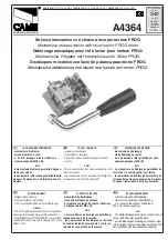
FROG series
Brand: CAME Pages: 2

GPS400
Brand: Wayne Pages: 8

UNIPRESS 4
Brand: Gates Pages: 54

DR-15-12
Brand: Mean Well Pages: 5

Mikasa MVC82VE
Brand: MULTIQUIP Pages: 60

301051L
Brand: SW-Stahl Pages: 12

AIR DUEL
Brand: Cannondale Pages: 12

ZM600-HP
Brand: ZALMAN Pages: 4

FCP
Brand: Feider Machines Pages: 15

ARM 450
Brand: Garland Pages: 16

PS902
Brand: Schlage Pages: 4

GE-CS 18 Li-Solo
Brand: EINHELL Pages: 44

ECE01113
Brand: Larzep Pages: 8

AS-100P
Brand: S.R.Smith Pages: 3

ECT113
Brand: Equalizer Pages: 6

FF1-D
Brand: Timberline Tool Pages: 6

11PTHH
Brand: Cleco Pages: 42

PBSG 95 E6
Brand: Parkside Pages: 96


