


Read this manual before using product. Failure to
follow instructions and safety precautions can
result in serious injury, death, or property
damage. Keep manual for future reference.
Part Number: GNA-2538 R0
Revised: March 2022
Original Instructions
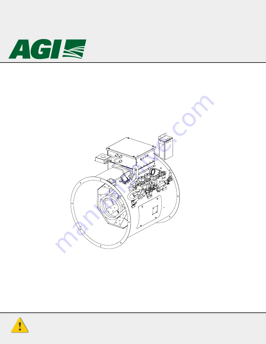
Axial Fan Heater
LP and NG-Fired Heater
Installation, Operation, and Parts Manual
INSTALLATION AND WIRING MUST BE IN
ACCORDANCE WITH CEC, NEC, AND LOCAL
ELECTRICAL CODES


