AG Neovo EH-24, User Manual
The AG Neovo EH-24, a high-performance monitor, offers exceptional visual clarity and vibrant colors. Ensure optimal use of its advanced features with the comprehensive User Manual available for free download from our website. Find all the essential instructions and settings to maximize your viewing experience at manualshive.com.
Share
Download


Reviews:
No comments
Related manuals for EH-24

732N - LCD Analog Display
Brand: Samsung Pages: 79

2243WM - SyncMaster - 22" LCD Monitor
Brand: Samsung Pages: 18

2233RZ - Syncmaster 22" 3D Gaming LCD Monito
Brand: Samsung Pages: 54

943BWX - SyncMaster - 19" LCD Monitor
Brand: Samsung Pages: 71

RADIFORCE RX220
Brand: Eizo Pages: 46
1029
Brand: Xenarc Pages: 16
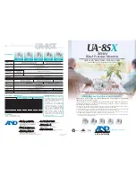
UA-851
Brand: A&D Pages: 2

UA-621
Brand: A&D Pages: 2
Viiiiva
Brand: 4iiii Pages: 2

L750
Brand: Daewoo Pages: 19

L700C
Brand: Daewoo Pages: 12

L510B1
Brand: Daewoo Pages: 36

HL510S
Brand: Daewoo Pages: 70
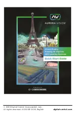
Aurora Vision
Brand: DCI Pages: 8

SMART Board 2000 series
Brand: Smart Technologies Pages: 60

DINOS DN109/P
Brand: Ditel Pages: 2

VZ-TFT-7
Brand: VARIZOOM Pages: 2

AOD/ATS 190w
Brand: A1 Touch Pages: 14


