

Quick Start Guide, 61200570L1-13C, November 2006
Copyright © 2006 ADTRAN, All Rights Reserved
For more detailed documentation, visit us online at
.
Quick Start Guide
®
NetVanta 1224 Power over Ethernet Series
P/N 1200530L1/1200570L1/
1200580L1/1200584L1
G
ETTING
S
TARTED
Two configuration methods are available for your NetVanta switch:
•
Web-based GUI
•
AOS Command Line Interface (CLI)
The GUI lets you configure the main unit settings and provides online guidance and explanations for
each setting. However, using the AOS CLI may be necessary for more advanced configurations.
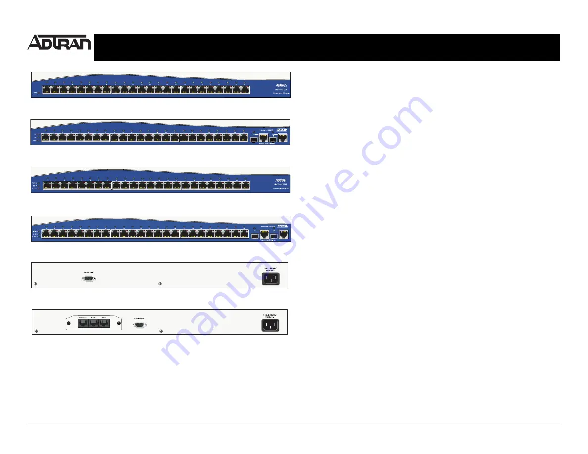
N
ET
V
ANTA
1224 P
O
E F
RONT
P
ANEL
L
AYOUT
N
ET
V
ANTA
1224STR P
O
E F
RONT
P
ANEL
L
AYOUT
N
ET
V
ANTA
1224R P
O
E F
RONT
P
ANEL
L
AYOUT
N
ET
V
ANTA
1224 P
O
E
AND
1224ST P
O
E R
EAR
P
ANEL
L
AYOUT
N
ET
V
ANTA
1224R P
O
E
AND
1224STR P
O
E R
EAR
P
ANEL
L
AYOUT
A
CCESS
THE
GUI
You may access the web-based GUI from any web browser on your network by following these
steps:
1.
Connect the switch to your PC using any of the 24 Ethernet ports on the front of the unit.
2.
Set your PC to a fixed IP address of 10.10.10.2. If you cannot change the PC’s IP address,
you will need to change the unit’s IP address using the CLI. (Refer to the next two sections
for instructions.)
3.
Enter the unit’s IP address in your browser address line. The default IP address is
10.10.10.1.
4.
You will then be prompted for the username and password (the default settings are
admin
and
password
).
5.
The initial GUI screen appears.
A
CCESS
THE
CLI
Access the AOS CLI via the
CONSOLE
port or a Telnet session. To establish a connection to the
NetVanta switch
CONSOLE
port, you need the following items:
•
VT100 terminal or PC (with VT100 terminal emulation software)
•
Straight-through serial cable with a DB-9 (male) connector on one end and the appropriate
interface for your terminal or PC communication port on the other end
1.
Connect the DB-9 (male) connector of your serial cable to the
CONSOLE
port on the rear
panel of the unit.
2.
Connect the other end of the serial cable to the terminal or PC.
3.
Insert the connector of the provided power cord into the power interface on the rear panel of
the unit, and plug the cord into a standard electrical outlet.
4.
Once the unit is powered up, open a VT100 terminal session using the following settings:
9600 baud, 8 data bits, no parity bits, and 1 stop bit. Press
<Enter>
to activate the AOS CLI.
5.
Enter
enable
at the
>
prompt.
6.
Enter the enable password when prompted. The default password is
password
.
P
OWER
OVER
E
THERNET
Power over Ethernet (PoE) switches provide the ability to detect attached Powered Devices (PD)
and deliver 48 VDC to the PD via existing CAT5 cabeling. The PoE devices are fully compliant with
the IEEE 802.3af Power over Ethernet standard. By default, the PoE switches discover and
provide power to IEEE compliant PDs.
To disable power detection and supply, use the
power inline never
command in the CLI. To
disable power detection and supply from the GUI, click on the
Ports
page. Then click on a single
port from the list (e.g.,
eth 0/1
). This will bring up the port detail page for
eth 0/1
. On this page,
there is a check box to enable power detection.
N
ET
V
ANTA
1224ST P
O
E F
RONT
P
ANEL
L
AYOUT


