Express 5210
Frame Relay Service Unit
User Manual
61200208L1-1A
October 1999
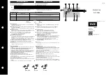
1200208L1
Base Unit
1202187L1
Dual FXO Card
1202188L1
Dual FXS Card
1202189L1
Dual E&M Card
1204001L1
4-wire SW56 DBU Card
1204002L1
V.34 DBU Card
1204004L1
ISDN DBU Card
1204006L1
External DCE Card
1200193L1
V.35 Adapter Cable (male)
1200194L1
V.35 Adapter Cable (female)
Summary of Contents for Express 5210
Page 10: ...x Express 5210 User Manual 61200208L1 1...
Page 18: ...Table of Contents xviii Express 5210 User Manual 61200208L1 1...
Page 22: ...Table of Contents xxii Express 5210 User Manual 61200208L1 1...
Page 30: ...Chapter 1 Introduction 1 8 Express 5210 User Manual 61200208L1 1...
Page 36: ...Chapter 2 Installation 2 6 Express 5210 User Manual 61200208L1 1...
Page 50: ...Chapter 3 Menu Navigation 3 14 Express 5210 User Manual 61200208L1 1...
Page 76: ...Chapter 6 Configuration Overview 6 4 Express 5210 User Manual 61200208L1 1...
Page 98: ...Chapter 7 DTE Port Configuration 7 22 Express 5210 User Manual 61200208L1 1...
Page 104: ...Chapter 8 Voice Configuration 8 6 Express 5210 User Manual 61200208L1 1...
Page 114: ...Chapter 9 Network Port Configuration 9 10 Express 5210 User Manual 61200208L1 1...
Page 162: ...Chapter 14 Testing 14 8 Express 5210 User Manual 61200208L1 1...
Page 176: ...Appendix B Specifications Summary B 6 Express 5210 User Manual 61200208L1 1...
Page 180: ...Appendix C Acronyms Abbreviations C 4 Express 5210 User Manual 61200208L1 1...
Page 202: ...Index Index 14 Express 5210 User Manual 61200208L1 1...