


Conflicts With Other Options
Your host adapter and all other peripherals may
not use or occupy overlapping memory and I/O
addresses:
1. IRQ and DMA Channels may be altered with the
Configuration Software.
2. Port addresses and BIOS addresses for the host
adapter may be viewed with the Configuration
Software and changed with the switch block on
the adapter board.
7
Switch Block Settings
Settings controlled by the switch block on the up-
per left-hand corner of the host adapter board are
as follows:
sw1
On
Termination Installed
sw5
On
Disable Floppy
✢
Off
Software Controlled*
Off
Enable Floppy*
sw2 sw3 sw4 I/O Port
sw6 sw7 sw8 BIOS Address
Off
Off
Off
330–333h*
Off
Off
Off
DC000h*
On
Off
Off
334–337h
On
Off
Off
D8000h
Off
On
Off
230–233h
Off
On
Off
D4000h
On
On
Off
234–237h
On
On
Off
D0000h
Off
Off
On
130–133h
Off
Off
On
CC000h
On
Off
On
134–137h
On
Off
On
C8000h
Off
On
On
Reserved
Off
On
On
Reserved
On
On
On
Reserved
On
On
On
BIOS Disable
Off
= Open
* = Standard setting: Standard settings on your
host adapter may be different; Adaptec custom con-
figures for proprietary customers and resellers.
✢
= Standard on AHA-1540C
•
A table and text explaining host adapter termi-
nation can be found in sections and
Note
If switch sw1 is switched to On, host adapter termina-
tion will always be enabled regardless of the setting in
the Configuration Software.
8
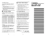
Adaptec Customer Support
•
The Adaptec Electronic Bulletin Board Service (BBS)
provides information on software upgrades, new re-
leases, technical advice, and more.
The BBS can be reached at: (408) 945-7727,
1200/2400/9600 baud, 8 data bits, 1 stop bit, no parity.
•
The Adaptec Technical Support Hot Line can be
reached at (408) 945-2550.
•
Additional documentation for Adaptec products can be
requested by calling (800) 934-2766.
FCC Compliance Statement
NOTE: This equipment has been tested and found to comply
with the limits for a Class B digital device, pursuant to Part 15
of the FCC rules. These limits are designed to provide reason-
able protection against harmful interference in residential in-
stallations. This equipment generates, uses, and can radiate
radio frequency energy, and if not installed and used in accord-
ance with the instructions, may cause harmful interference to
radio communications. However, there is no guarantee that in-
terference will not occur in a particular installation.
If this equipment does cause interference to radio or television
equipment reception, which can be determined by turning the
equipment off and on, the user is encouraged to try to correct
the interference by one or more of the following measures:
•
Reorient or relocate the receiving antenna
•
Move the equipment away from the receiver
•
Plug the equipment into an outlet on a circuit different
from that to which the receiver is powered
•
If necessary, the user should consult the dealer or an
experienced radio/television technician for additional
suggestions
CAUTION: Only equipment certified to comply with Class B
(computer input/output devices, terminals, printers, etc.)
should be attached to this equipment, and must have shielded
interface cables.
Finally, any change or modifications to the equipment by the
user not expressly approved by the grantee or manufacturer
could void the user’s authority to operate such equipment.
691 south milpitas blvd.
•
milpitas, california
•
95035
Printed in Singapore
Stock No.:510217-00 Rev.B CL7/92
AHA-1540C/1542C
Installation Guide
2
3
10
11


