Actisense PRO-MUX-1, How To Configure
The Actisense PRO-MUX-1 user manual is essential for understanding how to configure this versatile multiplexer. Download the comprehensive manual for free from manualshive.com, ensuring that you grasp the product's capabilities and unleash its full potential.
Share
Download


Reviews:
No comments
Related manuals for PRO-MUX-1

SunPro CP7678
Brand: Actron Pages: 36

SDM-160
Brand: Samsung Pages: 42

SDM-090
Brand: Samsung Pages: 69

OC 505
Brand: Orbit Controls Pages: 23

UT61D
Brand: UNI-T Pages: 5

BENNING MM 6
Brand: PEWA Pages: 66

KMDS02
Brand: koban Pages: 8

TC8614
Brand: TC Communications Pages: 39

ColorPlex-16
Brand: Elmo Pages: 2

197A
Brand: Keithley Pages: 61

DRA-RTM-8
Brand: Omega Pages: 12

45218
Brand: Wiha Pages: 185
82005
Brand: Craftsman Pages: 22
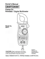
82011
Brand: Craftsman Pages: 12

MM 7
Brand: Benning Pages: 142

NV-DVR1600
Brand: Novus Pages: 88

VIP-882-V-TS
Brand: Vetra Pages: 2

Keithley 3700A Series
Brand: Tektronix Pages: 18


