


STAND-ALONE DVR
ALL ABOUT IMAGE RECOGNITION & PROCESSING
User manual
VER 1.0
Thank you for purchasing our product.
Please read this user manual before
using the product.
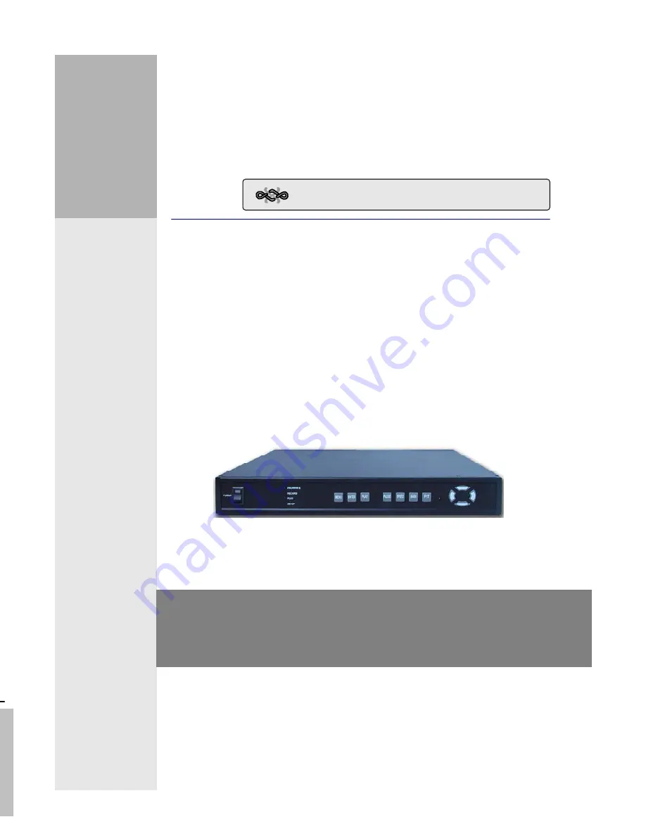
Single channel
stand-alone DVR
D
IG
IT
A
L
V
IDE
O
RE
CO
R
DE
R
D
IGITAL VID
E
O R
E
C
OR
D
ER
1 Channel Stand-Alone DVMR
ALL ABOUT IMAGE RECOGNITION & PROCESSING
Comply with Multiplexers
Best solution to replace Time Lapse VCR in use with Multiplexer
Single Channel Digital Video Recorder


