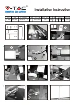
Important Safeguards:
WARNING – When using electrical equipment, basic safety precautions should always be used including the following:
This product must be installed in accordance with the applicable installation code by a person familiar with the construction
and operation of the product and the hazards involved.
READ AND FOLLOW ALL SAFETY INSTRUCTIONS
P3330
Rev 1/16
SAVE THESE INSTRUCTIONS
Technical Support: 888 / 387-2212
1300 S Wolf Road, Des Plaines, Illinois, 60018 / 220 Chrysler Drive, Brampton, Ontario L6S 6B6 ©2016 Acuity Brands Lighting, Inc.
Figure 3
Figure 2
Figure 1
❶
Disconnect Power
• Disconnect Power during installation and maintenance.
❷
Prepare Luminaire for Mounting
• Open the wiring compartment by removing the two screws (
A1
) (see Figure 1)
❸
Install Bolster Plate
Figure 2 & 3
• Using the nut and long bolt (1) attach the bolster plate to the pole as illustrated
❹
Secure Wiring
• Insert wires through wireway
• Tether the wires using the cable tie
➁
mounted on the bolster plate.
❺
Mount the Luminaire
• Hang luminaire on bolt
➀
Note the position of the two washers
• Secure bolt
➀
finger tight
• Align the bolster plate and attach the short bolt
➂
• Tighten bolts
➀
and
➂
❻
Check Voltage
• Connect leads to proper voltage
• Attach the appropriate leads to the terminal block mounted on the wiring
compartment door (
A4
) (See figure 1)
• Individually cap all unused leads.
• Close the wiring compartment
Aiming the Optics
Unless pre-aimed at the factory (options RL or RR), standard fixtures are shipped
with optics aimed to the front. If a different orientation is needed, the optics can
be field rotated 90 degrees to the right or to the left. To rotate the optics, follow
these steps:
❶
Loosen the screws (
A2
) securing the Driver Housing Cover (
A3
) (see Figure 1)
and remove cover
❷
Loosen the 4 bolts (
A5
) securing the LED Housing to the Driver Housing.
After all 4 bolts are removed the LED housing will drop about ¼” allowing
for rotation.
❸
Rotate 90 degrees in any direction
❹
Insert back all 4 bolts (
A5
) to secure the LED Housing to the Driver Housing
and tighten.
❺
Close the Driver Housing Cover (
A3
)
Important Safeguards:
WARNING – When using electrical equipment, basic safety precautions should alwats be used including the following:
This product must be installed in accordance with the applicable installation code by a person familiar with the construction
and operation of the product and the hazards involved.
READ AND FOLLOW ALL SAFETY INSTRUCTIONS
Mark means lamp contains mercury.
Follow disposal laws.
See www.lamprecycle.org
Hg
Z-12108
Rev 5 1-1-08
®
SAVE THESE INSTRUCTIONS
Technical Support: 888 / 387-2212
1300 S Wolf Road, Des Plaines, Illinois, 60017 / 219 Shoemaker Street, Kitchener, Ontario, N2E 3B3 / 220 Chrysler Drive, Brampton, Ontario L6S 6B6
Pole
Drilling
Pattern
3”
MIN
1-1/2”
3”
Ø 7/16”
(x2)
Ø 1”
Pole
Bolster Plate
(This end is
unthreaded)
Lock washer
Bolster Plate
(This end is
threaded)
Luminaire
Flat washer
Lock washer
➁
Cable Tie
Flat washer
Lock washer
➂
1-3/4” Bolt
➀
2-1/4” Bolt
Nut
Figure 2
Polycarbonate Guard
• Remove door assembly
from the luminaire
• Locate the four dimples in
the corners of the door and
drill clearance holes for a
#6 screw.
• Assemble and attach the
polycarbonate guard as
illustrated.
Drill
here
Nut
Lock Washer
Door
Spacer
Flat Washer
Polycarbonate Guard
Flat Washer
Screw
External House Side Shield
Note: External House Side Shield is not suitable for
Forward Throw distribution - order an Internal
House Side Shield (Suffix ‘-SH’)
• Remove door assembly from
the luminaire
• Locate the dimples in the door
and drill using the #6 bit
provided.
• Attach the house side shield
using the screws provided.
Drill
here
Drill
here
Figure 1
❶
Disconnect Power
• Disconnect Power during installation and maintenance.
❷
Prepare Luminaire for Mounting
• Open door assembly.
• Remove protective plastic from the reflector sides
• Disconnect Safety Cable from door assembly.
• Swivel door assembly to
approximately 50˚ and remove.
• For ease of installation, the tray mounted ballast may also be removed. Hold
tray with one hand while loosening the thumb screw and let hang. Move past
90˚ to remove.
❸
Install Bolster Plate
Figure 1 & 2
• Using the nut and long (2-1/4”) bolt
➀
, attach the bolster plate as illustrated.
❹
Secure Wiring
• Insert cable through wireway
• Tether the cable using the cable tie
➁
mounted on the bolster plate.
❺
Mount the Luminaire
• Hang luminaire on bolt
➀
Note the position of the two washers
• Secure bolt
➀
finger tight
• Align the bolster plate and attach the short (1-3/4”) bolt
➂
• Tighten bolts
➀
and
➂
❻
Check Voltage
•
Luminaires with multi-tap ballasts are factory wired to the highest voltage.
For other voltages, ensure correct leads are used.
• Connect leads to proper voltage.
• Attach the appropriate leads using approved connectors.
• Individually cap all unused leads.
❼
Orient Optics
• If optical assembly is not
oriented correctly, remove by
loosening four screws to and
rotate as illustrated
❽
Replace Door and Safety Cable
• Align door assembly at approximately 50˚ and re-mount.
• Re-attach the safety cable
➒
Install Lamp
• Tighten lamp securely.
• Observe the lamp manufacturers recommendations and restrictions.
• Remove and install compact fluorescent lamps by grasping only the plastic
portion of the lamp.
❿
Close Door Assembly
• Close and secure snap action latch
LEFT FACING
RIGHT FACING
FORWARD
Areos
™
LED
Installation Instructions
A2
Screws
A5
Bolts
A3
Cover
A1
Screws
A4
Wiring Cover